2-8 Cisco 4000 Series Hardware Installation and Maintenance
Preparing to Make Connections
If the Token Ring module in Figure 2-2 was replaced by a second Ethernet module, the unit
addresses would be as listed in Table 2-2.
Table 2-2 Unit Numbering Addresses for Dual Serial and Two Ethernet Modules
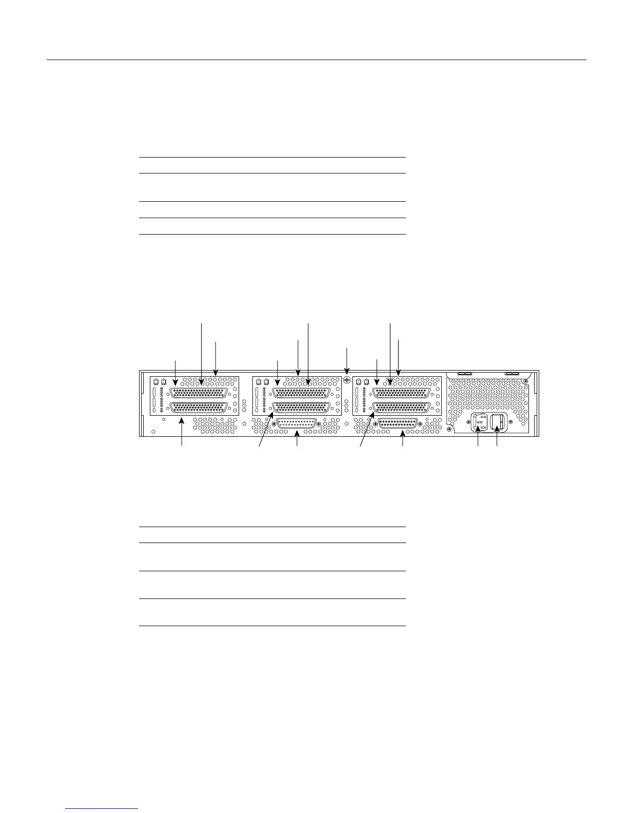
Figure 2-3 shows a chassis configured with three dual serial modules.
Figure 2-3 Router—Rear View Showing Serial Port Unit Numbering
The unit numbering of these modules would be as listed in Table 2-3.
Table 2-3 Unit Numbering Addresses for Three Dual Serial Modules
If the router is configured with fewer than three network processor modules, you must place a slot
filler panel in the open slot to ensure proper airflow. Figure 2-4 shows a slot filler panel.
Slot No. Interface Type Unit Address No.
1 Serial Port (Top)
Serial Port (Bottom)
1
0
2Ethernet 0
3Ethernet 1
Slot No. Interface Type Unit Address No.
1 Serial Port (Top)
Serial Port (Bottom)
1
0
2 Serial Port (Top)
Serial Port (Bottom)
3
2
3 Serial Port (Top)
Serial Port (Bottom)
5
4
Chassis
release screw
Auxiliary port Console port Power On/off switch
H1402 a
AUX CONSOLE
INPUT 100-240VAC 50/60HZ 3.0-1.5 AMPS
Dual serial module Dual serial module
Slot 3 Slot 2 Slot 1
Serial 1
Serial 0
Dual serial module
Serial 3
Serial 5
Serial 2Serial 4