Troubleshooting the Initial Hardware Configuration 4-9
Reading Network Processor Module LED Indicators
The convention used here to indicate corresponding signals for DTE/DCE is to list DTE first. For
example, Figure 4-9 shows the top LED, D0, indicates TXD in DTE mode or RXD in DCE mode.
The dual serial port network processor module LED Indicators are explained in Table 4-2.
Table 4-2 Dual Serial Network Processor Module LED Indicators
FDDI Network Processor Module LED Indicators
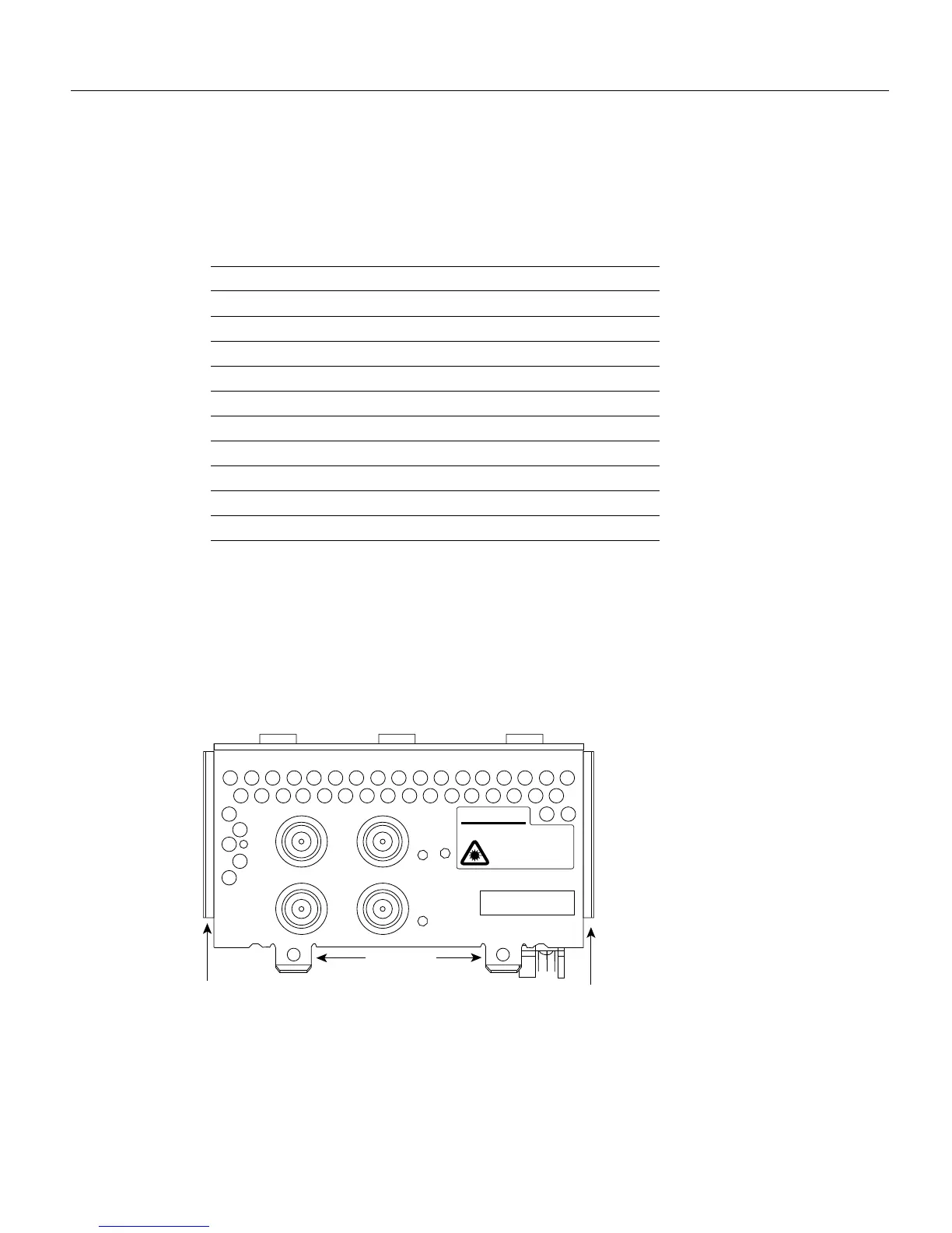
Dual-attachment FDDI network processor modules have one LED per port, located adjacent to the
corresponding port on the module panel (see Figure 4-10 and Figure 4-11), while single-attachment
modules have one LED, located adjacent to the single port on the module panel. (See Figure 4-12.)
Figure 4-10 Dual-Attachment Single-Mode FDDI Module—End View
Serial LED Card Outer Labels Indication (DTE/DCE)
DO Data Out (TXD/RXD)
TXC Transmit Clock
DI Data In (RXD/TXD)
RXC Receive Clock
DCD Data Carrier Detect
RS Receive Signaling
TS1 Transmit Signaling
TS2 Transmit Signaling
LP Loop
DCE Lit if network processor module is DCE
H1614a
PHY-B
PHY-A
Alignment groove
Mounting
screw locations
Alignment groove
XMTR RCVR
AVOID EXPOSURE–INVISIBLE
LASER RADIATION IS EMITTED
FROM THESE APERTURES.
PHY–B
RING OP
PHY–A
RING OP
FDDI
WARNING
CISCO SYSTEMS, INC.
170 WEST TASMAN DRIVE
SAN JOSE, CA 95134-1706
DATE:
“Complies with FDA Radiation
Performance Standards, 21 CFR,
Subchapter J”
1300
NM
CLASS 1 LASER PRODUCT
LASERKLASSE 1