4-10 Cisco 4000 Series Hardware Installation and Maintenance
Reading Network Processor Module LED Indicators
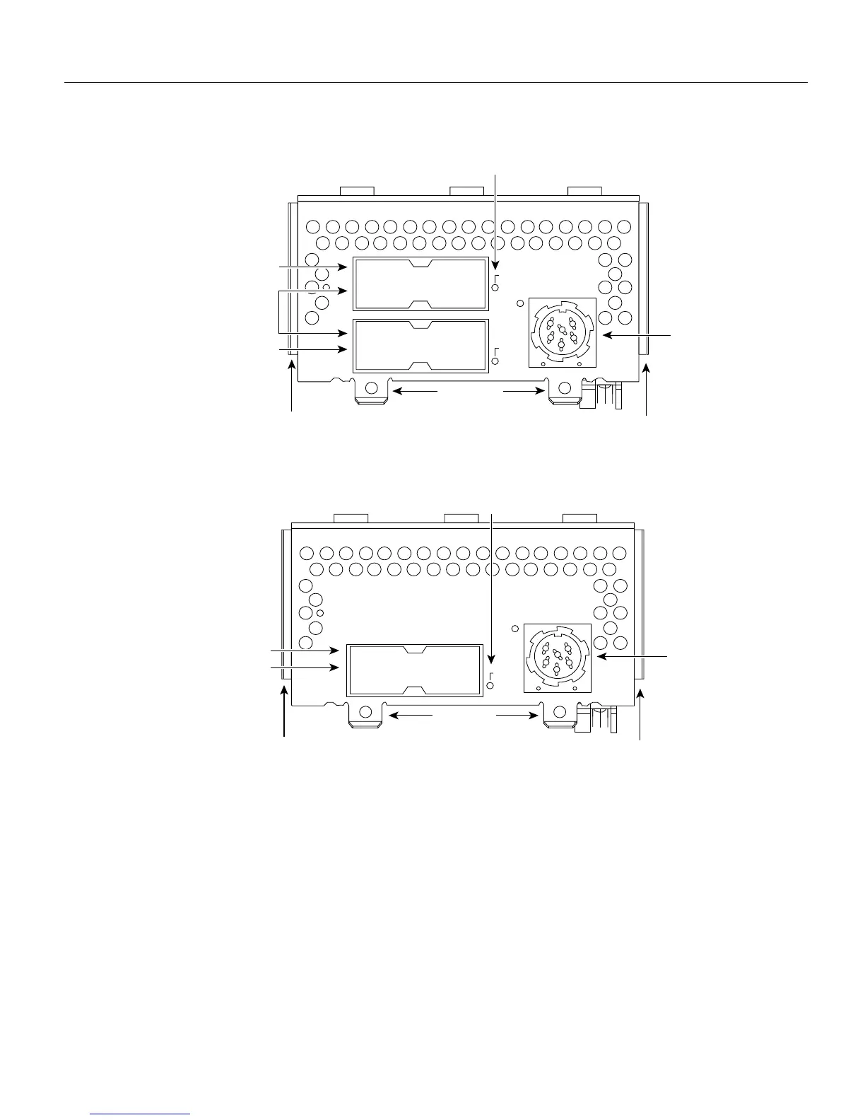
Figure 4-11 Dual-Attachment Multimode FDDI Module—End View
Figure 4-12 Single-Attachment Multimode FDDI Module—End View
When lit, a module LED indicates a ring up condition. Dual-attachment FDDI module LEDs
indicate which PHY on the network processor module is inserted into the ring; if a PHY is not
actively inserted into the ring, the LED is not lit. On a single-attachment module, the LED indicates
ring up when lit; when the LED is not lit, it indicates that the module is not inserted into a ring.
H1400a
PHY-B
PHY-A
FDDI
OPT-BYPASS
Multimode ports
Alignment groove
Alignment groove
Optical bypass
switch connector
LEDs (2)
PHY-B
PHY-A
PHY-B
RING OP
PHY-A
RING OP
Mounting
screw locations
H1401a
PHY-S
FDDI
OPT-BYPASS
Multimode port
Alignment groove
Alignment groove
Optical bypass
switch connector
LED
PHY-S
PHY-S
RING OPT
Mounting
screw locations