4-8 Cisco 4000 Series Hardware Installation and Maintenance
Reading Network Processor Module LED Indicators
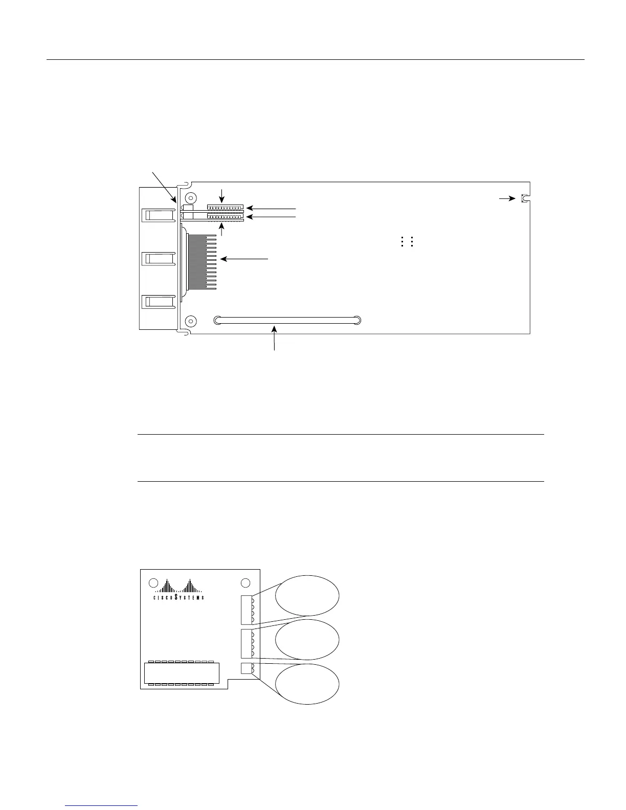
Figure 4-8 shows the top view of the dual serial network processor module. Note the locations of the
LED daughter cards and the ports that they indicate.
Figure 4-8 Dual Serial Network Processor Module—Top View
When DCE cables are used and when the port is configured in software with the clockrate command
as a DCE port, the bottom LED will light. (See Figure 4-9.) (For a further explanation of the
clockrate command, see the appropriate Cisco IOS software publication.)
Note An error message will be generated if there is a mismatch between the cable and the software
configuration of the port—for example, if the cable is DTE and the clock rate is set, or if the cable
is DCE and the clock rate is not configured.
Figure 4-9 shows the dual serial port network processor module LED card.
Figure 4-9 Dual Serial Port LED Card—Side View
LED daughter cards
Serial
ports
H1777
Module handle
Mounting
screw location
LEDs
Port 1
Port 0
J5
J4
Indicates port 0
Indicates Port 1
XX Serial LED
78-0851-01 REV
DO
TXC
DI
RXC
DCD
RS
TS1
TS2
LP
DCE
H1046a