Preparing for Installation 2-27
Network Connection Considerations
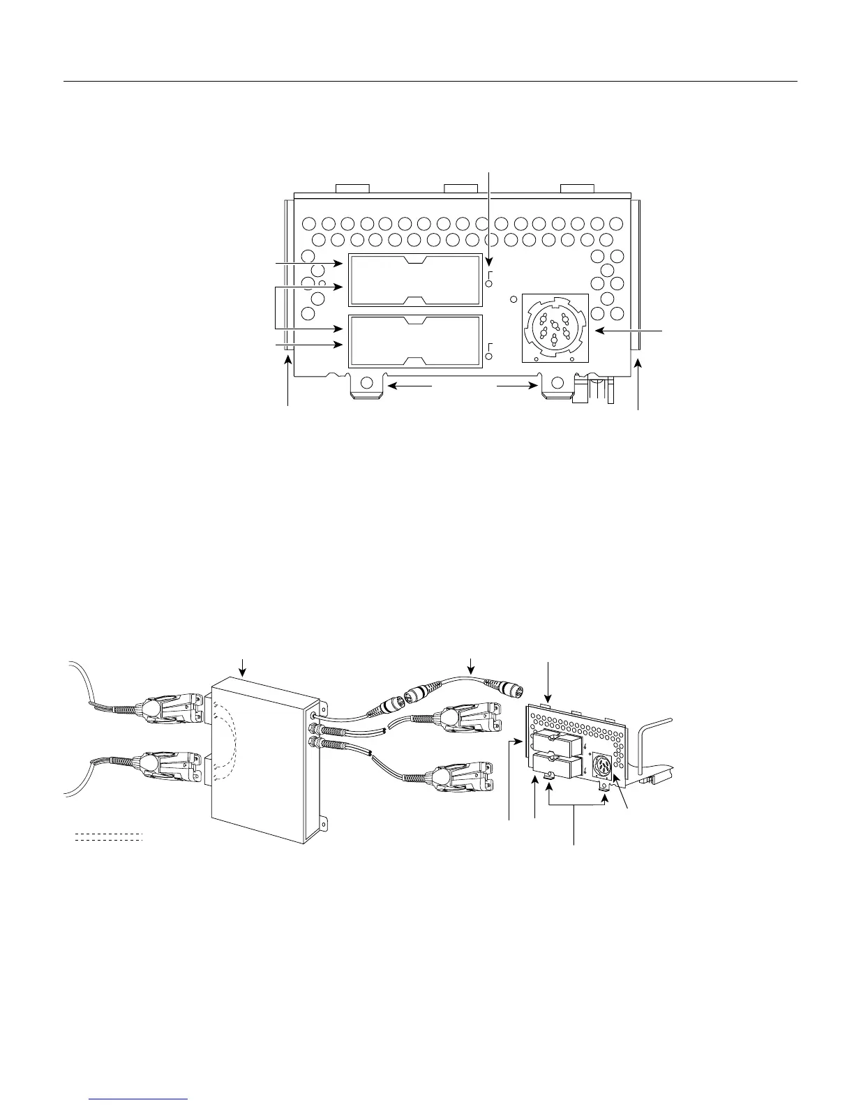
Figure 2-27 Dual-Attachment Multimode FDDI Module—End View
The standard connection scheme for a dual-attachment station dictates that the primary ring signal
enters the router on the PHY-A RCVR port and returns to the primary ring from the PHY-B XMTR
port. (See Figure 2-28.) The secondary ring signal comes into the router on the PHY-B RCVR port
and returns to the primary ring from the PHY-A XMTR port. Failure to observe this relationship in
making your network connections will prevent the FDDI interface from initializing.
The single-attachment module’s PHY-S port can be connected through a concentrator to a
single-attachment ring, or can be connected point-to-point directly to another device.
Figure 2-28 Dual-Attachment FDDI Optical Bypass Switch and PHY Connections
The single-attachment module’s PHY-S port (as shown in Figure 2-29) can be connected through a
concentrator to a single-attachment ring or directly to another device.
H1400a
PHY-B
PHY-A
FDDI
OPT-BYPASS
Multimode ports
Alignment groove
Alignment groove
Optical bypass
switch connector
LEDs (2)
PHY-B
PHY-A
PHY-B
RING OP
PHY-A
RING OP
Mounting
screw locations
Optical bypass
switch
PHY-B
PHY-B
Bypass operation
To
ring
P
H
Y
-B
P
H
Y
-A
R
I
N
G
O
P
R
I
N
G
O
P
FDDI
OPT-BYPASS
Optical
bypass switch
connector (DIN)
Dual-attachment
multimode
FDDI module
H1405a
Optical bypass
interface cable
PHY-A
PHY-A
Mounting
screw locations