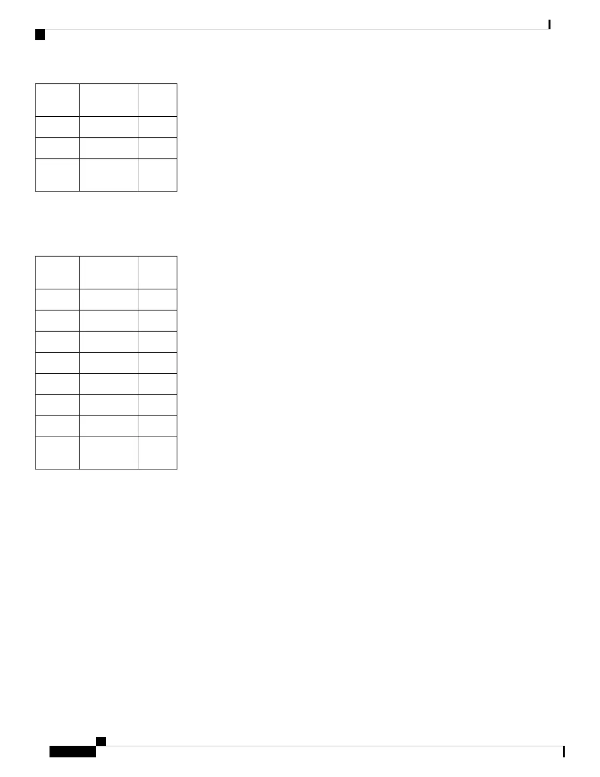
DB9
Pins
Wire ColorRJ-45
Pins
3Yellow6
8Brown7
7White or
Gray
8
Note: Table 21: RJ45 to DB9 Male Adapter, on page 73 describes the pinouts for a RJ45 to DB9 (male)
Adapter. This allows connection from a local RJ45 DTE port to a far-end DCE DB9 port.
Table 22: RJ45 to DB9 Female Null Modem Adapter
DB9
Pins
Wire ColorRJ-45
Pins
4Blue1
1Orange2
6Black3
5Red4
3Green5
2Yellow6
7Brown7
8White or
Gray
8
Note: Table 22: RJ45 to DB9 Female Null Modem Adapter, on page 74 describes the pinouts for a RJ45 to
DB9 (female) Null Modem Adapter. This allows connection from a local RJ45 DTE port to a far-end DTE
DB9 port.
Place the pins into their proper sockets using the pinning tool, and when that is complete you should have a
connector that looks similar to the picture in Figure 48: Completed Pinning, on page 75.
IR1101 Industrial Integrated Services Router Hardware Installation Guide
74
Connecting the Router
RJ-45 Adapter Side