EasyManuals Logo

Cisco MDS 9132T User Manual

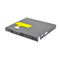
Cisco MDS 9132T
82 pages
To Next Page IconTo Next Page
To Previous Page IconTo Previous Page
Page #25 background imageLoading...
Page #25 background image
A roof-mounted fan tray and an air cooling scheme in which the fan tray pulls air in at the bottom of
the cabinet and exhausts it out the top, with a minimum of 849.5 m
3
/h of airflow exiting the cabinet roof
through the fan tray.
Nonperforated (solid and sealed) front and back doors and side panels so that air travels predictably
from bottom to top.
The overall cabinet depth should be 36 to 42 in. (91.4 to 106.7 cm) to allow the doors to close and
adequate airflow.
A minimum of 150 sq. in. (968 sq. cm) of open area at the floor air intake of the cabinet.
The lowest piece of equipment should be installed a minimum of 1.75 in. (4.4 cm) above the floor
openings to prevent blocking the floor intake.
Cisco MDS 9132T Fibre Channel Switch Hardware Installation Guide
19
Cabinet and Rack Installation
Requirements Specific to Solid-Walled Cabinets

Table of Contents

Other manuals for Cisco MDS 9132T

Questions and Answers:

Question and Answer IconNeed help?

Do you have a question about the Cisco MDS 9132T and is the answer not in the manual?

Cisco MDS 9132T Specifications

General IconGeneral
AirflowFront-to-back
Product TypeFibre Channel Switch
Rack-mountableYes
ManageableYes
Product ModelMDS 9132T
Operating Temperature32°F to 104°F (0°C to 40°C)
Storage Temperature-40°F to 158°F (-40°C to 70°C)
Power SupplyAC
Data Transfer Rate32 Gbps
Fibre Channel StandardFC-FS-2, FC-GS-4, FC-SW-2
Humidity5% to 93% (non-condensing)
Ports32 x 32Gbps Fibre Channel
Form Factor1U
Dimensions1.72 x 17.3 x 19.2 in
Port Speed32 Gbps
Weight17.6 lbs (8 kg)

Related product manuals