EasyManuals Logo

Cisco MDS 9132T User Manual

Cisco MDS 9132T
82 pages
To Next Page IconTo Next Page
To Previous Page IconTo Previous Page
Page #40 background imageLoading...
Page #40 background image
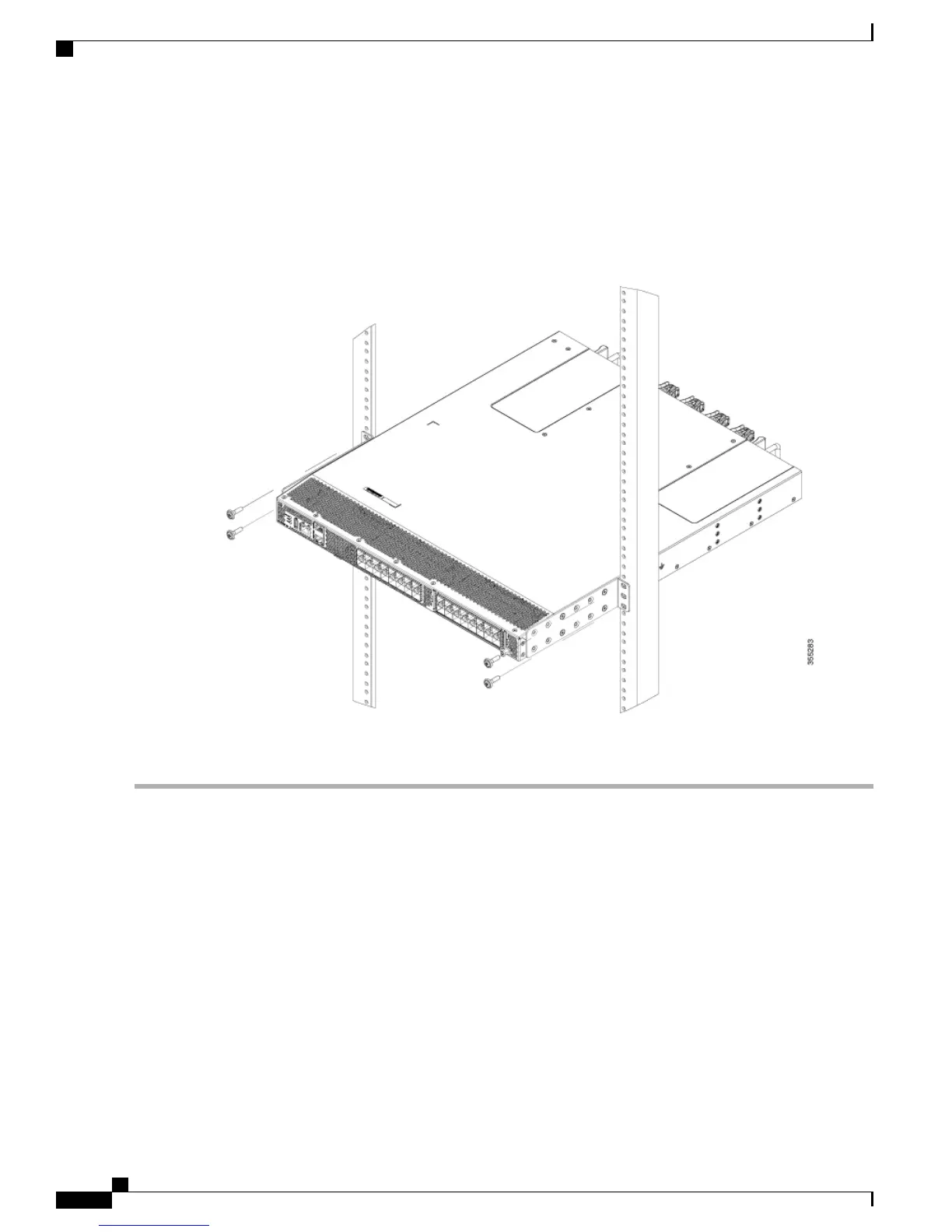
b) Holding the chassis level, insert two screws (12-24 or 10-32, depending on the rack type) in each of the two front
rack-mount brackets (using a total of four screws) and into the cage nuts or threaded holes in the vertical rack-mounting
posts.
Figure 14: Installing the switch onto the 2-post rack
c) Tighten the 10-32 screws to 20 in-lb (2.26 N.m) or tighten the 12-24 screws to 30 in-lb (3.39 N.m)
Removing the Shelf Bracket Kit (Optional)
The shelf bracket kit can be removed after the Cisco MDS 9132T switch has been installed in a four-post EIA
rack, and both front rack-mount brackets and both C brackets are securely attached to the rack-mounting posts.
Cisco MDS 9132T Fibre Channel Switch Hardware Installation Guide
34
Installing the Cisco MDS 9132T Switch
Removing the Shelf Bracket Kit (Optional)

Table of Contents

Other manuals for Cisco MDS 9132T

Questions and Answers:

Question and Answer IconNeed help?

Do you have a question about the Cisco MDS 9132T and is the answer not in the manual?

Cisco MDS 9132T Specifications

General IconGeneral
AirflowFront-to-back
Product TypeFibre Channel Switch
Rack-mountableYes
ManageableYes
Product ModelMDS 9132T
Operating Temperature32°F to 104°F (0°C to 40°C)
Storage Temperature-40°F to 158°F (-40°C to 70°C)
Power SupplyAC
Data Transfer Rate32 Gbps
Fibre Channel StandardFC-FS-2, FC-GS-4, FC-SW-2
Humidity5% to 93% (non-condensing)
Ports32 x 32Gbps Fibre Channel
Form Factor1U
Dimensions1.72 x 17.3 x 19.2 in
Port Speed32 Gbps
Weight17.6 lbs (8 kg)

Related product manuals