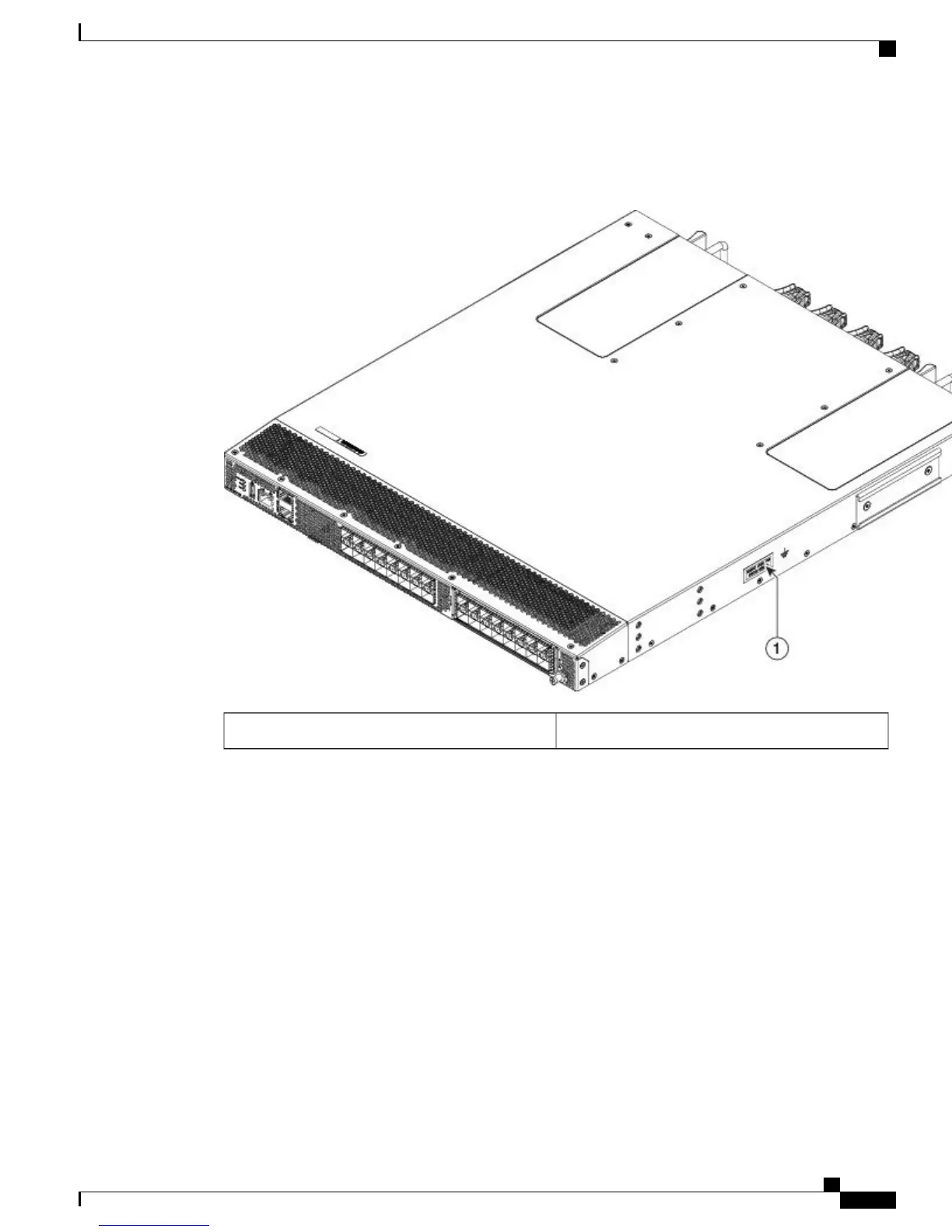
The following figure shows the grounding point of the Cisco MDS 9132T Switch:
Figure 3: Grounding point of the Cisco MDS 9132T Switch
Grounding point1
•
Fan Modules, page 7
•
Power Supplies, page 9
•
Linecard Expansion Module, page 10
•
Switch LEDs, page 12
•
Supported SFP+ Transceivers, page 16
Fan Modules
The Cisco MDS 9132T Switch fan modules have a fixed handle for inserting and removing from the chassis.
The Cisco MDS 9132T Switch requires a minimum of two operating fan modules to prevent automatic
shutdown. It supports installation of up to four fan modules. This provides redundancy for uninterrupted
operation in the event of fan module failure. The Cisco MDS 9132T Switch fan modules are hot-swappable
to allow swapping out of a fan module during operation for uninterrupted operation. Fan blank modules must
be installed in empty fan bays when operating for longer than several minutes to provide correct airflow. If
Cisco MDS 9132T Fibre Channel Switch Hardware Installation Guide
7
Product Overview
Fan Modules