EasyManuals Logo

Cisco MDS 9132T User Manual

Cisco MDS 9132T
82 pages
To Next Page IconTo Next Page
To Previous Page IconTo Previous Page
Page #78 background imageLoading...
Page #78 background image
Switzerland
12G SEV 1011 (10
A)
8Europe
VIIG Plug, CEE (7) VII (16 A)
4
Jumper Power Cord
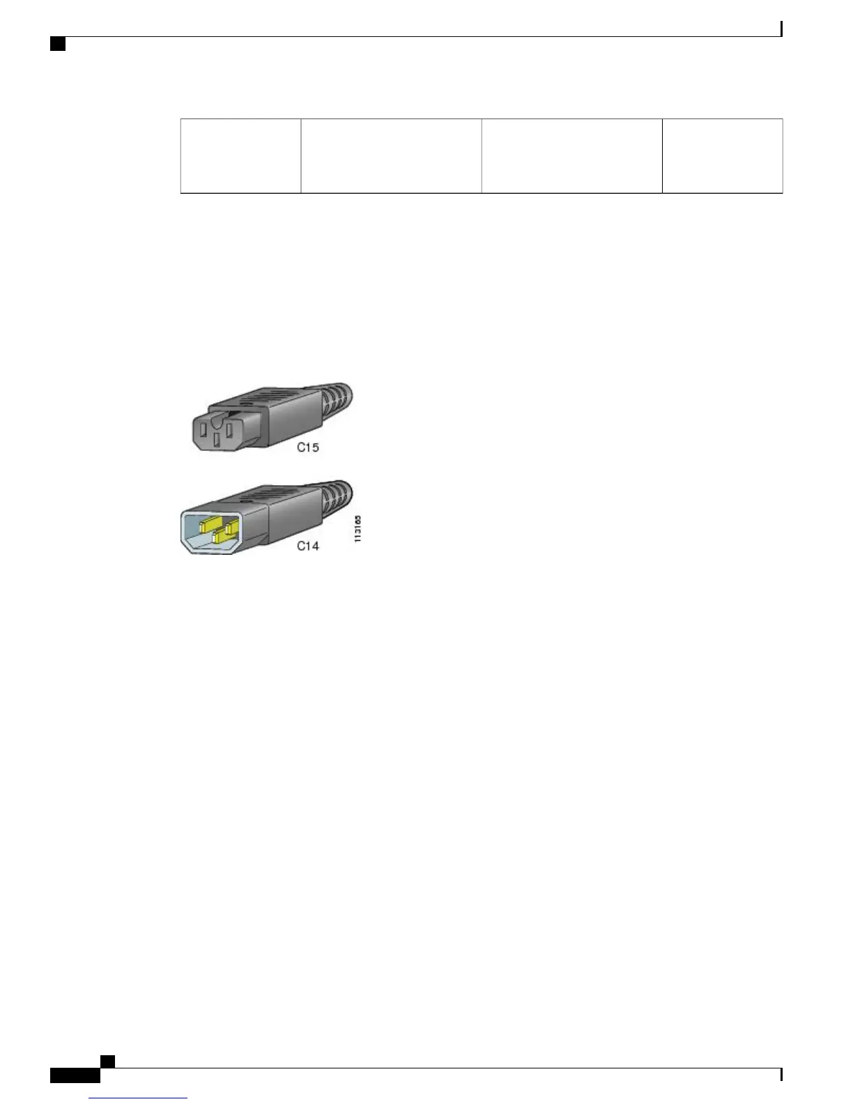
The following figure shows the C14 and C15 connectors on the optional jumper power cord for the Cisco
MDS 9132T Switch. The C15 connector connects into the C14 inlet on the Cisco MDS 9132T Switch power
supply, while the C14 connector connects into the C13 receptacle of a power distribution unit for a cabinet.
Figure 23: Connectors on Jumper Power Cord for Cisco MDS 9132T Switch
Cisco MDS 9132T Fibre Channel Switch Hardware Installation Guide
72
Cable and Port Specifications
Jumper Power Cord

Table of Contents

Other manuals for Cisco MDS 9132T

Questions and Answers:

Question and Answer IconNeed help?

Do you have a question about the Cisco MDS 9132T and is the answer not in the manual?

Cisco MDS 9132T Specifications

General IconGeneral
AirflowFront-to-back
Product TypeFibre Channel Switch
Rack-mountableYes
ManageableYes
Product ModelMDS 9132T
Operating Temperature32°F to 104°F (0°C to 40°C)
Storage Temperature-40°F to 158°F (-40°C to 70°C)
Power SupplyAC
Data Transfer Rate32 Gbps
Fibre Channel StandardFC-FS-2, FC-GS-4, FC-SW-2
Humidity5% to 93% (non-condensing)
Ports32 x 32Gbps Fibre Channel
Form Factor1U
Dimensions1.72 x 17.3 x 19.2 in
Port Speed32 Gbps
Weight17.6 lbs (8 kg)

Related product manuals