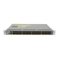
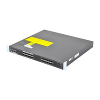
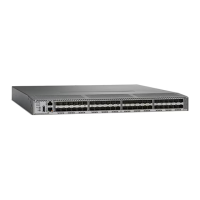
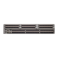
If you attached a grounding cable to the chassis, you will need to bend one of the rack-mount posts slightly
to allow the grounding lug to go behind the post.
Note
3
Holding the chassis level, insert two screws (12-24 or 10-32, depending on the rack type) in each of the two front
rack-mount brackets (using a total of four screws) and into the cage nuts or threaded holes in the vertical rack-mounting
posts.
4
Tighten the 10-32 screws to 20 in-lb (2.26 N·m) or tighten the 12-24 screws to 30 in-lb (3.39 N·m).
Step 6
If you attached a grounding wire to the chassis grounding pad, connect the other end of the wire to the facility ground.
Installing the Switch in a 2-Post Rack
Before You Begin
Step 1
Install two rack–mount brackets on to the switch as follows:
a) Determine which end of the chassis is to be located in the cold aisle as follows:
•
If the switch has port-side intake modules (fan modules with red coloring), position the switch so that its ports
will be in the cold aisle.
•
If the switch has port-side exhaust modules (fan modules with blue coloring), position the switch so that its fan
and power supply modules will be in the cold aisle.
b)
Position a rack–mount bracket so that four of its screw holes are aligned to the screw holes on the side of the chassis.
Then secure the front-mount bracket to the chassis using four M4 screws
Cisco MDS 9132T Fibre Channel Switch Hardware Installation Guide
31
Installing the Cisco MDS 9132T Switch
Installing the Switch in a 2-Post Rack

 Loading...
