For information on how to failover a supervisor module, see the Cisco MDS 9000 Family NX-OS Fundamentals
Configuration Guide.
Step 2 Put the standby supervisor module to out of service before removing the standby supervisor module, using the
out-of-service moduleslot command.
Where slot indicates the chassis slot number in which the standby supervisor module resides.
switch(config)# out-of-service module 5
Step 3 Disconnect any network interface cables attached to the module.
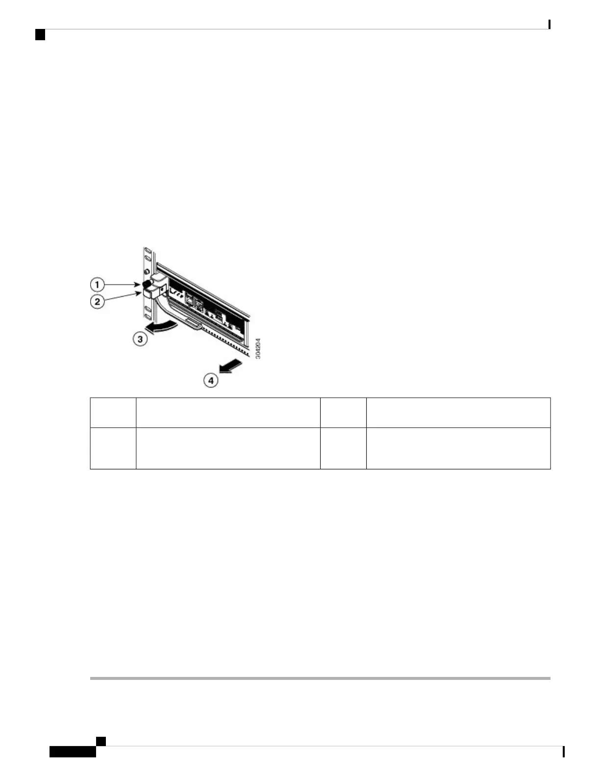
Step 4 Unscrew the captive screw on the left side of the module until the screw is no longer connected to the chassis (see
Callout 1 in the following figure).
Figure 46: Removing a Half-width Supervisor Module
The handle springs open.3Unscrew the captive screw until it is free of
the chassis.
1
Pull the handle to remove the module part way
from the slot. Place your other hand under the
module and fully remove it from the slot.
4Press the ejector button.2
Step 5 Press the ejector release button on the left of the module (see Step 2 in the above figure) to push out the ejector lever.
The ejector springs out part way from the front of the module.
Step 6 Fully rotate the handle from the front of the module and pull the handle to move the module part way out of its slot.
Step 7 Place your other hand under the module to support its weight and pull the module fully out of its slot. Do not touch the
module circuitry.
Step 8 Place the module on an antistatic mat or antistatic foam.
Step 9 Install a filler panel on an empty slot to keep the chassis dust-free and to maintain proper airflow through the chassis.
Blank faceplates and cover panels serve three important functions: they prevent exposure to hazardous
voltages and currents inside the chassis; they contain electromagnetic interference (EMI) that might disrupt
other equipment; and they direct the flow of cooling air through the chassis. Do not operate the system
unless all cards, faceplates, front covers, and rear covers are in place. Statement 1029
Warning
Step 10 Insert a new supervisor module in the empty slot and power on the standby supervisor module. To see how to install a
supervisor module, see the Installing a Supervisor Module, on page 113.
Cisco MDS 9700 Series Switches Hardware Installation Guide
116
Installing, Removing, and Verifying Field Replaceable Units
Removing a Supervisor Module
 Loading...


