Step 1 Verify that the shelf brackets are level and securely attached to the rack-mounting rails, the crossbar is securely attached
to the shelf brackets, and the rack is stabilized.
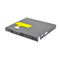
Step 2 Slide the switch onto the shelf brackets, ensuring that it is squarely positioned.
Step 3 Attach the Cisco MDS 9700 Series switch to the rack-mounting rails. Slide the clip nuts over the holes on the nonthreaded
rails on the rack. These clip nuts provide the threading for the screws that will secure the chassis to the rack. Use the12
10-32 x 1/2 inch screws provided in this shelf bracket kit to secure the chassis to the rack.
We recommend that grounding the chassis, even if the rack is already grounded. There is a grounding pad
with two threaded M4 holes on the chassis for attaching a grounding lug.
Caution
Removing the Shelf Bracket Kit
Use this procedure to remove the shelf bracket kit.
The shelf bracket kit can be removed after the Cisco MDS 9700 Series switch has been installed in a two-post
telco (only MDS 9706 Director) or four-post EIA rack, and the front rack-mount brackets are securely attached
to the rack-mounting rails. For additional support in an EIA rack, ensure that the C brackets on the Cisco
MDS 9710 Switch are attached to the rear rack-mounting rails.
Step 1 Remove the screws fastening the slider brackets to the rear rack-mounting rails. Then slide the slider brackets out of the
shelf brackets.
Step 2 Remove the screws fastening the crossbar to the shelf brackets and remove the crossbar.
Step 3 Remove the screws fastening the shelf brackets to the front rack-mounting rails. Then remove the shelf brackets from
the rack.
Cisco MDS 9700 Series Switches Hardware Installation Guide
74
Preparing the Site
Removing the Shelf Bracket Kit

 Loading...
