b. Continue to push in the line card slowly into the chassis until its rear connectors touch the mid-plane surface and
both ejector levers swing inward about 25 degrees. This indicates that both the ejector lever jaws are now inside the
chassis jaw cutouts and the card is ready to close the ejector levers.
c. Once visually confirmed that both ejector levers are swung inward about 25 degrees, push in both ejector levers
simultaneously to fully insert the line card into the chassis until they are in a mechanically locked position. Both
ejector levers should be parallel to the line card faceplate when locked.
Ensure that the ejector levers are fully closed before tightening the captive screws. Failure to fully seat
the module in the backplane connector can result in error messages.
Note
d. Tighten the two captive screws on the supervisor module or switching module to 8 in-lb.
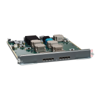
Removing a Switching Module
You can remove one of these modules at a time while the switch is operating. To remove a switching module
from the chassis, follow these steps:
Before you begin
You need a flat-blade or number 2 Phillips-head screwdriver to loosen or tighten the captive screws on the
switching module.
Step 1 Disconnect any network interface cables attached to the module.
Step 2 Loosen the two captive screws on the module being removed.
Step 3 Press ejector release buttons on the left and right ends of the module to push out the ejector levers and to disconnect the
module.
Step 4 Simultaneously rotate the two ejector levers outward to unseat the module from the mid-plane connector.
Step 5 With a hand on each ejector, pull the module part way out of its slot in the chassis.
Step 6 Grasp the front edge of the module and slide the module partially out of the slot. Place your other hand under the module
to support the weight of the module. Do not touch the module circuitry.
Step 7 Place the module on an antistatic mat or antistatic foam, or immediately reinstall it in another slot.
Step 8 If the slot will remain empty, install a filler panel to keep the chassis dust-free and to maintain proper airflow through
the chassis
Verifying Installation of the Supervisor and Switching Modules
To verify the module installation, follow these steps:
Step 1 Verify that the ejector levers of each module are fully closed (parallel to the front of the module) to ensure that the
supervisor module and all switching or services modules are fully seated in the backplane connectors.
Step 2 Check the captive screws of each module, the power supply, and the fan module. Tighten any loose captive screws to 8
in-lb.
Cisco MDS 9700 Series Switches Hardware Installation Guide
155
Installing, Removing, and Verifying Field Replaceable Units
Removing a Switching Module

 Loading...
