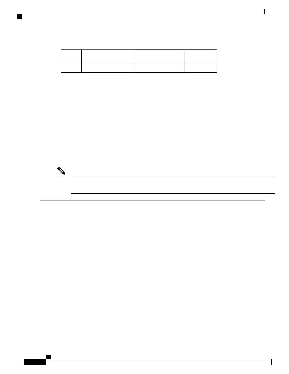
Table 19: Software Power Mode Grids Required
Full
Redundancy
Input Source RedundancyPower Supply RedundancyCombined
2211
For information about the software power configuration modes, refer to the “Supported Transceivers” section.
For information about the location of Grid A and Grid B power supply slots for each type of MDS 9700
Director chassis, refer to the chassis specific information at:
• Cisco MDS 9718 Chassis Front View
• Cisco MDS 9710 Chassis Front View
• Cisco MDS 9706 Chassis Front View
Before you connect a chassis power supply to an AC power source, ensure all of the following:
• There is a vacant receptacle on the AC power source within reach of the chassis power supply cable.
• The power supply is already installed in the chassis.
• The chassis is connected to an earth ground.
In a single phase AC power supply unit, connection of multiple phases from the same three-phase source is
supported and direct connection of three-phase is not supported.
Note
Step 1 Ensure that the power supply switch located on the front of the power supply is set at standby (labeled as 0).
Step 2 Plug one AC power cable into the power supply, and pull down the retention clip over the plug on the power cable.
Step 3 Plug the other end of the power cable into a AC power source supplied by the data center.
To reduce risk of electric shock and fire, take care when connecting units to the supply circuit so that wiring
is not overloaded. Statement 1018.
Warning
This product relies on the building’s installation for short-circuit (over current) protection. To reduce risk of
electric shock or fire, ensure that the protective device is rated not greater than: 250V, 20 A. Statement 1005.
Warning
Step 4 Turn the power supply switch from standby to on (from 0 to 1 as labeled on the power switch).
Step 5 Verify that the power supply is receiving AC power and outputting DC power by making sure that the INPUT and
OUTPUT power supply LEDs are lit and the FAULT LED is not lit or flashing. For an explanation of all the power
supply LEDs and the conditions that they indicate, see Table 1-15.
When you first activate the power supply, you can verify the functionality of the LEDs by checking that each
LED turns on for a couple of seconds.
Note
Cisco MDS 9700 Series Switches Hardware Installation Guide
170
Installing, Removing, and Verifying Field Replaceable Units
Connecting an AC Power Supply to an AC Power Source
 Loading...


