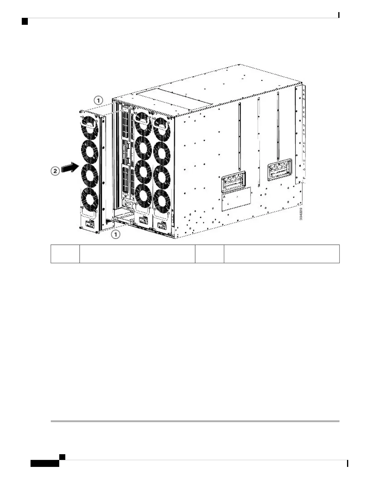
Figure 52: Installing a Fan Module
Press the whole fan module into the chassis slot.2Align the four pins in the fan module with four
holes in the chassis.
1
Step 3 With the electrical contacts on the fan module aligned to contacts on the backplane, press the fan module fully into the
slot.
Step 4 Screw in each of the four captive screws on the front of the fan module to secure the fan module to the chassis. After
fully engaged, tighten each screw to 8 in-lb (0.9 N·m) of torque.
Step 5 Listen for the fans; you should immediately hear them operating. If you do not hear them, ensure that the fan module is
inserted completely in the chassis and the outside surface of the fan module is flush with the outside surface of the chassis.
Step 6 Verify that the Fan Status LED is green. If the LED is not green, one or more fans are faulty. If this occurs, contact your
customer service representative for a replacement part.
Step 7 If the switch is powered on, listen for the fans; you should immediately hear them operating. If you do not hear them,
ensure that the fan module is inserted completely in the chassis and the outside surface of the fan module is flush with
the outside surface of the chassis.
Step 8 Verify that the Fan Status LED is green. If the LED is not green, one or more fans are faulty. If this occurs, contact your
customer service representative for a replacement part. For more information about the LED states, see the System LEDs
, on page 21.
If you purchased this product through a Cisco reseller, contact the reseller directly for technical support. If
you purchased this product directly from Cisco Systems, contact Cisco Technical Support at this URL:
http://www.cisco.com/en/US/support/tsd_cisco_worldwide_contacts.html.
Note
Cisco MDS 9700 Series Switches Hardware Installation Guide
176
Installing, Removing, and Verifying Field Replaceable Units
Installing a Fan Module
 Loading...


