MaximumTypicalComponent
504 W440 W32-port 100-Gigabit Ethernet QSFP28 line card (N9K-X9432C-S)–
Fan Trays
250 W176 W(N9K-C9508-FAN)–
900 W450 W(N9K-C9508-FAN2)–
Blank Fan Power Card
90 W45 W(N9K-C9508-FAN-PWR)–
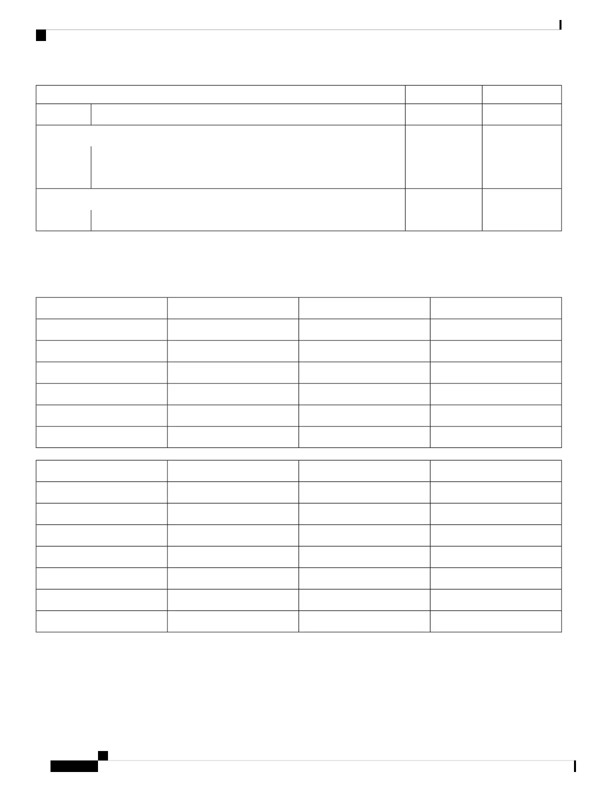
The system software reserves, by default, the maximum power required to power-on two Supervisors, two System
Controllers, and three fan trays (generation 1). The total required power budget for the chassis to boot would then be the
sum of the maximum power of all the fabric modules, fan trays, and line cards installed on the chassis. Here are two
examples:
Total PowerMax. PowerQuantityComponent
160 W80 W2N9K-SUP-B+
50 W25 W2N9K-SC-A
2,100 W420 W5N9K-C9508-FM-E2
750 W250 W3N9K-C9508-FAN
3,600 W900 W4N9K-X9736C-FX
6,660 WTotal System Power
Total PowerMax. PowerQuantityComponent
160 W80 W2N9K-SUP-B+
50 W25 W2N9K-SC-A
3,744 W936 W4N9K-C9508-FM-G
2,700 W900 W3N9K-C9508-FAN2
180 W90 W2N9K-C9508-FAN-PWR
6,720 W1,680 W4N9K-X9716D-GX
13,554 WTotal System Power
Step 2 Determine the number of power supplies required to power the modules that are installed in the switch by dividing the
module power requirement amount (see Step 1) by the output wattage (3000 W) of the power supplies installed in the
switch. Round up the fractional result to the nearest ones digit.
Cisco Nexus 9508 NX-OS Mode Switch Hardware Installation Guide
14
Preparing the Site
Planning for Power Requirements
 Loading...