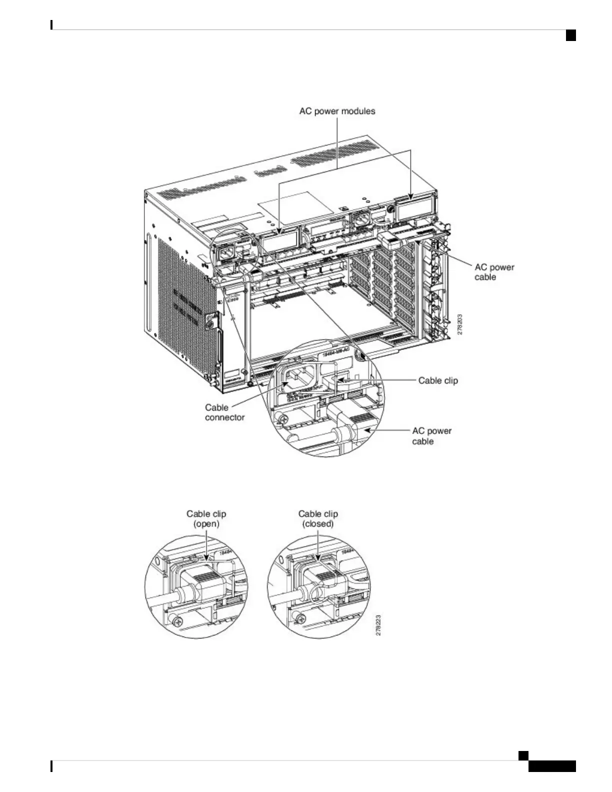
Figure 81: Connecting Office Power—AC Power Modules
Step 3 Close the cable clip to secure the power cable (see the following figure).
Figure 82: Cable Clip to Secure the Power Cable
For Slot A power module, the power cable exits from the left side. For Slot B power module, the
power cable exits from the right side (see the following figure).
Note
Installing the ONS 15454 M6 Shelf
105
Installing the ONS 15454 M6 Shelf
DLP-G571 Connect Office Power (AC) to the ONS 15454 M6 Shelf

 Loading...