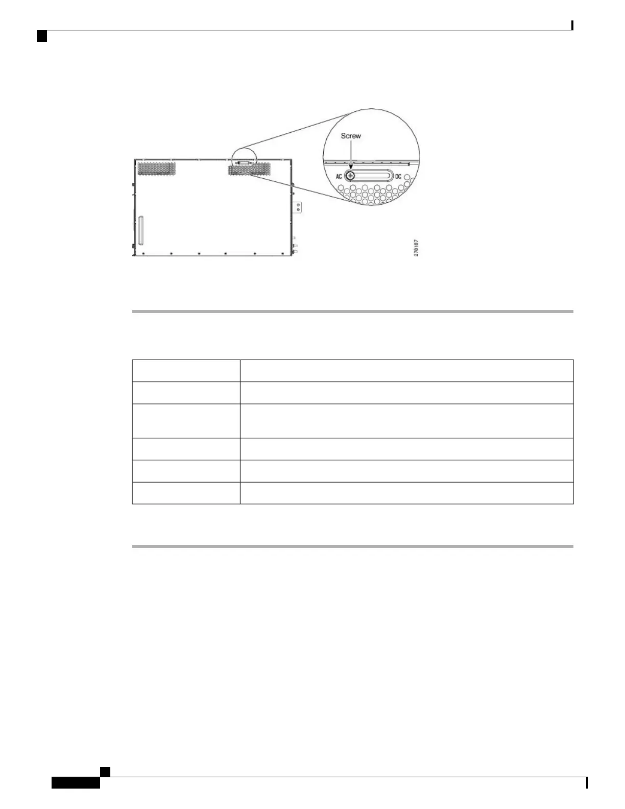
Figure 27: AC Power Module Installation—Rear Side of the ONS 15454 M6 Shelf
Step 2 Loosen the screw and move it to the left position (towards the AC silk-screen text).
Step 3 Tighten the screw again to a torque value of 4 in-lb (0.45 N-m).
DLP-G675 Verify the ONS 15454 M6 Shelf for DC Power Module Installation
This task verifies the shelf for DC power module installation.Purpose
NoneTools/Equipment
NTP-G305 Unpack and Inspect the ONS 15454, ONS 15454 M2, and ONS 15454
M6 Shelves
Prerequisite Procedures
RequiredRequired/As Needed
OnsiteOnsite/Remote
NoneSecurity Level
Procedure
Step 1 Verify the position of the mechanical locking system on the rear side of the chassis. To use the DC power
module the screw must be close to the DC silk-screen text (see the following figure).
Installing the ONS 15454 M6 Shelf
28
Installing the ONS 15454 M6 Shelf
DLP-G675 Verify the ONS 15454 M6 Shelf for DC Power Module Installation

 Loading...