The ECU module, power modules, LCD and the fan-tray assembly can be installed in any order.
Note
Step 2 Complete the DLP-G578 Inspect the ONS 15454 M6 Shelf Installation and Connections, on page 157.
Step 3 Complete the DLP-G579 Measure DC Voltage on the ONS 15454 M6 Shelf, on page 157.
Step 4 Continue with the Connect the PC and Log into the GUI document.
Stop. You have completed this procedure.
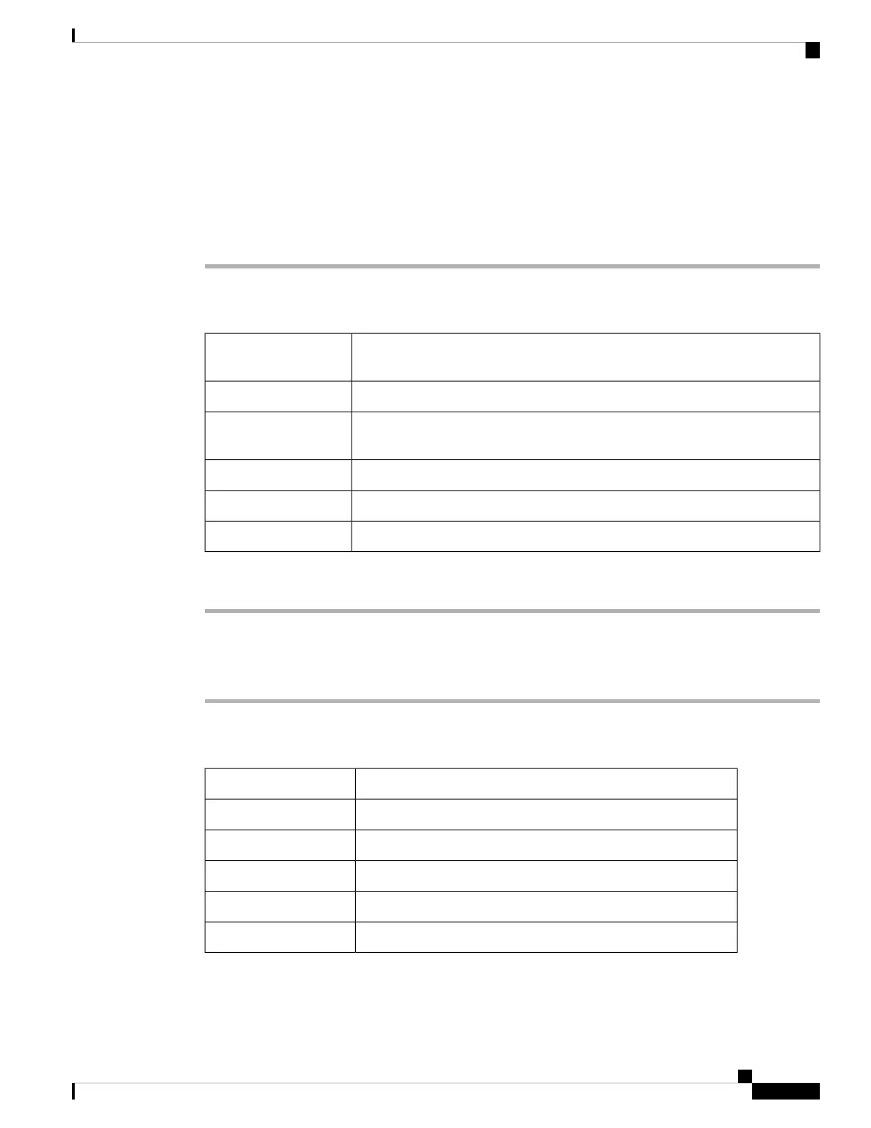
DLP-G578 Inspect the ONS 15454 M6 Shelf Installation and Connections
Use this task to inspect the shelf installation and connections and verify that
everything is installed and connected properly.
Purpose
NoneTools/Equipment
NonePrerequisite
Procedures
RequiredRequired/As Needed
OnsiteOnsite/Remote
NoneSecurity Level
Procedure
Step 1 Make sure all external wiring connections on the ECU module (that is, power, ground, alarms, and so on) are
secure. If a wire or cable is loose, return to the appropriate procedure in this chapter to correct it.
Step 2 Return to your originating procedure (NTP).
DLP-G579 Measure DC Voltage on the ONS 15454 M6 Shelf
Use this task to measure DC voltage on the ONS 15454 M6 shelf.Purpose
VoltmeterTools/Equipment
Before installing the DC power, check the voltagePrerequisite Procedures
RequiredRequired/As Needed
OnsiteOnsite/Remote
NoneSecurity Level
Installing the ONS 15454 M6 Shelf
157
Installing the ONS 15454 M6 Shelf
DLP-G578 Inspect the ONS 15454 M6 Shelf Installation and Connections

 Loading...