3-4
Cisco UCS C460 Server Installation and Service Guide
OL-22326-01
Chapter 3 Maintaining the Server
Status LEDs and Buttons
Operations Panel LEDs and Buttons
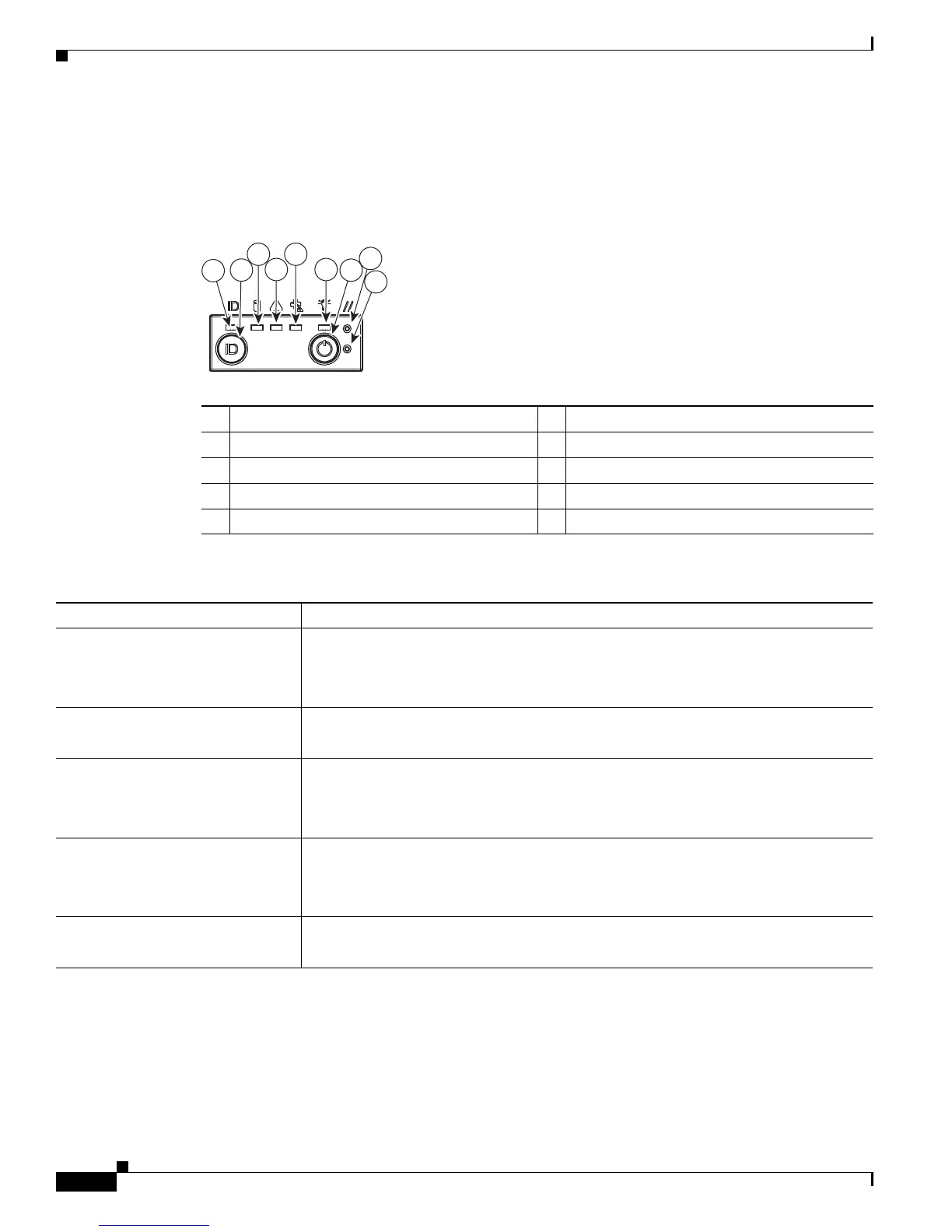
Figure 3-2 shows the operations panel LEDs and buttons.
Figure 3-2 Operations Panel LEDs and Buttons
1 ID LED 2 ID button
3 Hard drive fault LED 4 System health LED
5 Fan fault LED 6 Power status LED
7 Power button 8 Reset button
9 NMI button
Ta b l e 3-2 Operations Panel LEDs
LED Name State
ID • Off—The ID LED is not in use.
• Blue and blinking—System ID is active via the remote ID button.
• Blue and steady—System ID is active via the local ID button.
Hard drive fault • Green—No hard drives have a fault.
• Amber—At least one hard drive has failed.
System health • Green—The system is not in fault.
• Amber and steady—The system is in moderate fault.
• Amber and blinking—The system is in severe fault.
Fan fault • Off—All fan modules are operating properly.
• Amber—At least one fan module has a moderate fault.
• Amber, blinking—At least one fan module has a severe fault.
Power status • Off—The server is in standby power mode or no power is present.
• Green—The server is in main power mode.
12 7
8
9
35
197617
4 6

 Loading...