3-5
Cisco UCS C460 Server Installation and Service Guide
OL-22326-01z
Chapter 3 Maintaining the Server
Status LEDs and Buttons
Rear Panel LEDs and Buttons
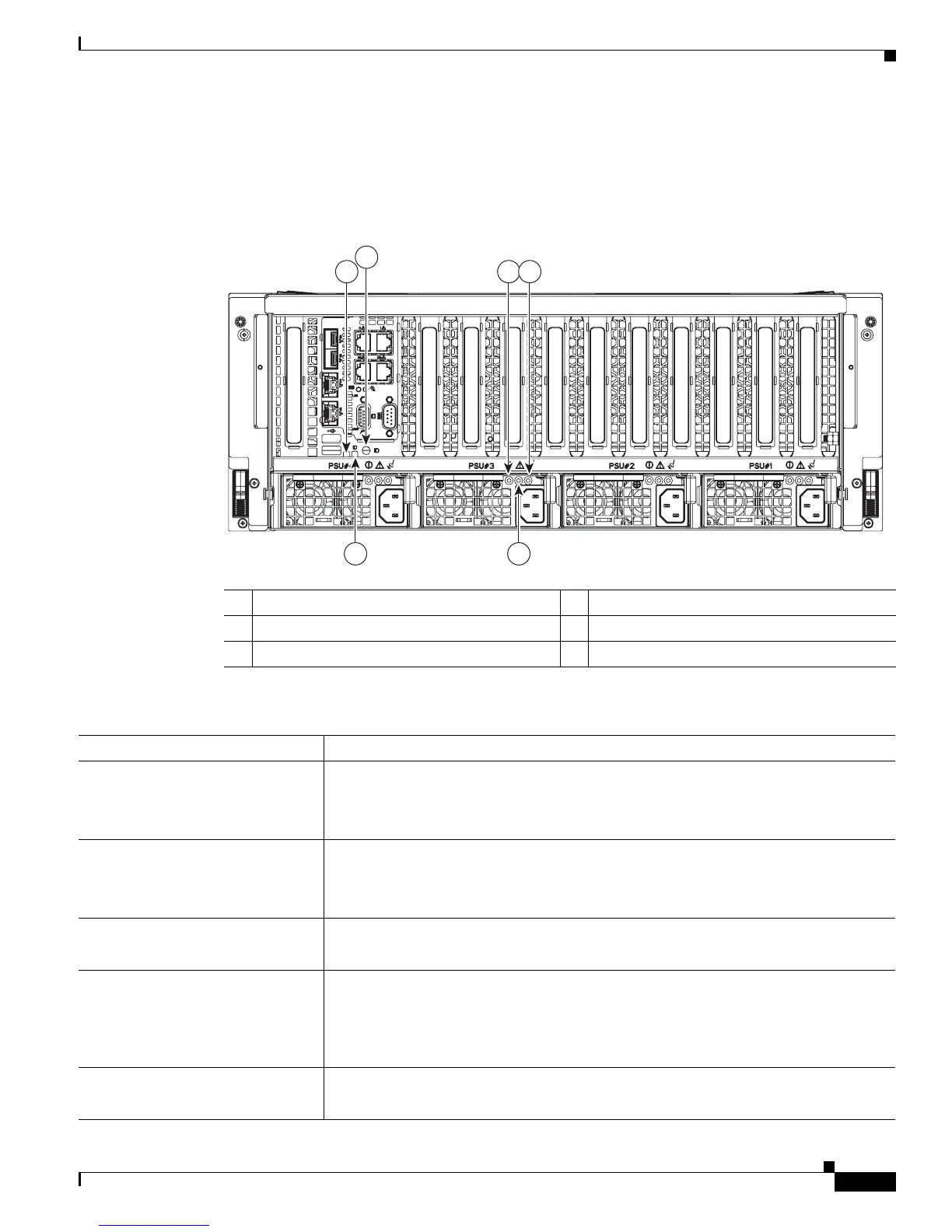
Figure 3-3 shows the rear panel LEDs and buttons.
Figure 3-3 Rear Panel LEDs and Buttons
1 System health LED 2 ID LED
3 ID button 4 Power supply status LED
5 Power supply fault LED 6 Power supply AC input LED
Ta b l e 3-3 Operations Panel LEDs
LED Name State
System health • Green—The system is not in fault.
• Amber and steady—The system is in moderate fault.
• Amber and blinking—The system is in severe fault.
ID • Off—The ID LED is not in use.
• Blue and blinking—System ID is active via the remote ID button.
• Blue and steady—System ID is active via the local ID button.
Power supply status LED • Green and steady—The server is in main power mode.
• Green and blinking—The power supply is off and it is in cold redundancy mode.
Power supply fault LED • Off—The power supply is operating properly.
• Amber and blinking—The power supply is warning of an event, but continues to
operate.
• Amber and steady—The power supply is in critical fault, causing a shut down.
Power supply AC input LED • Green and steady—The AC power cord is plugged in and the power is present.
• Green and blinking—The AC power cord is not plugged in.

 Loading...