3-8
Cisco UCS C460 Server Installation and Service Guide
OL-22326-01
Chapter 3 Maintaining the Server
Preparing for Server Component Installation
Replaceable Component Locations
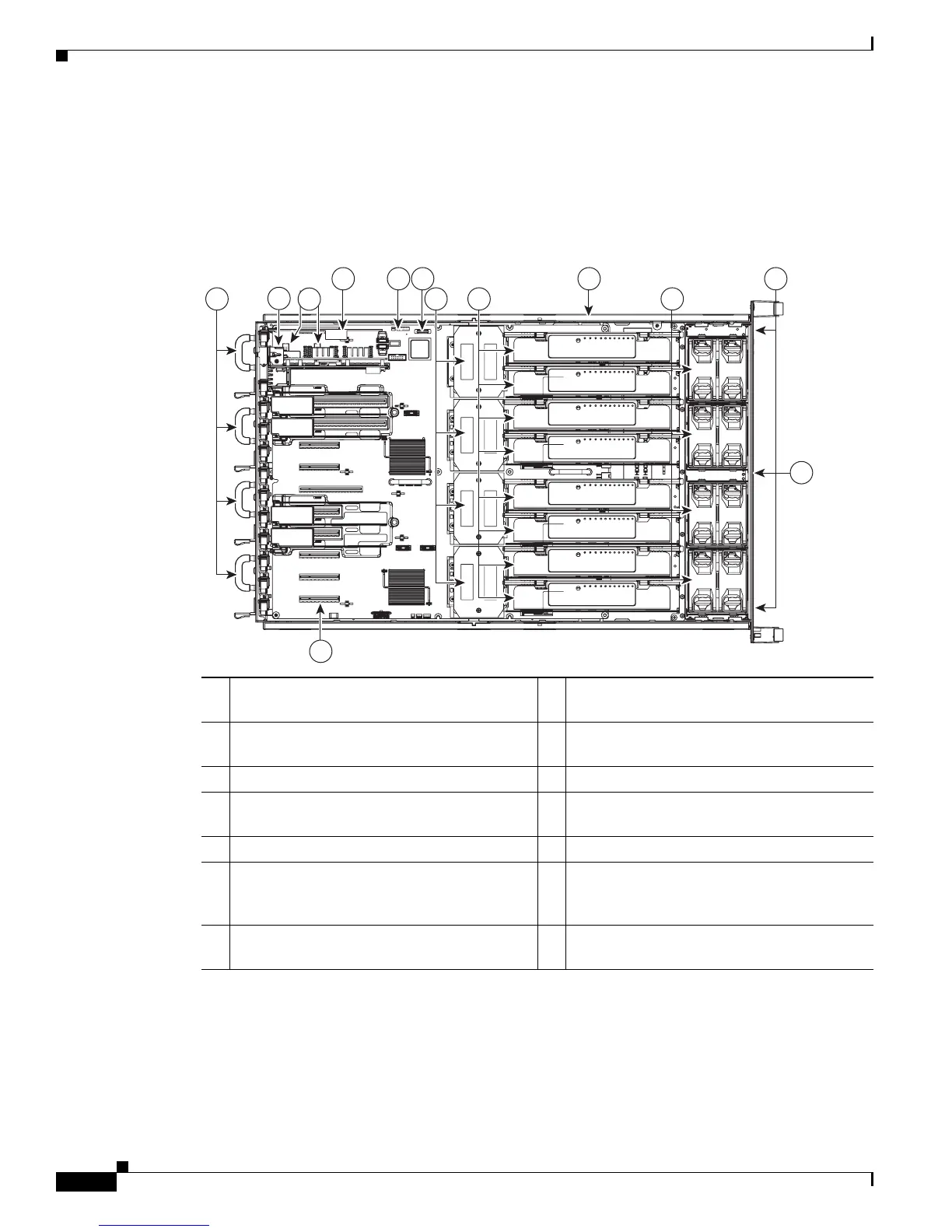
This section shows the locations of the components that are discussed in this chapter. The view in
Figure 3-5 is from the top down, with the top cover and internal CPU cage removed.
Figure 3-5 Replaceable Component Locations
1 Power supplies, up to 4 (accessed through the
rear panel).
8 Memory risers, which provide slots for up to
8 DIMMs on each riser.
2 I/O riser module. 9 RAID battery backup unit (optional when
using the LSI 9260 controller)
3 eUSB connectors (2 on motherboard). 10 Fan modules (up to 8)
4 SAS riser (a dedicated slot for the RAID
controller card)
11 Hard drives (up to 12, accessed through the
front panel)
5 Trusted Platform Module (TPM) header 12 DVD drive (accessed through the front panel)
6 CMOS battery 13 PCIe connector 10 (10 of 10)
See also Figure 3-27 on page 3-38 for all slot
locations and details.
7 CPUs and heat sinks (up to 4, shown without
CPU cage)
2
4 5 6 9
12
1 1087
11
198709
3
13

 Loading...