3-30
Cisco UCS C460 Server Installation and Service Guide
OL-22326-01
Chapter 3 Maintaining the Server
Installing or Replacing Server Components
DIMM Installation Procedure
This section contains the following topics:
• Identifying a Faulty DIMM, page 3-30
• DIMM Replacement Procedure, page 3-30
Identifying a Faulty DIMM
The memory riser has LEDs on it supper surface that can assist you in isolating a faulty DIMM. The
faulty DIMMs are indicated by the DIMM fault LEDs, which light amber to indicate which DIMMs are
faulty. See
Figure 3-20.
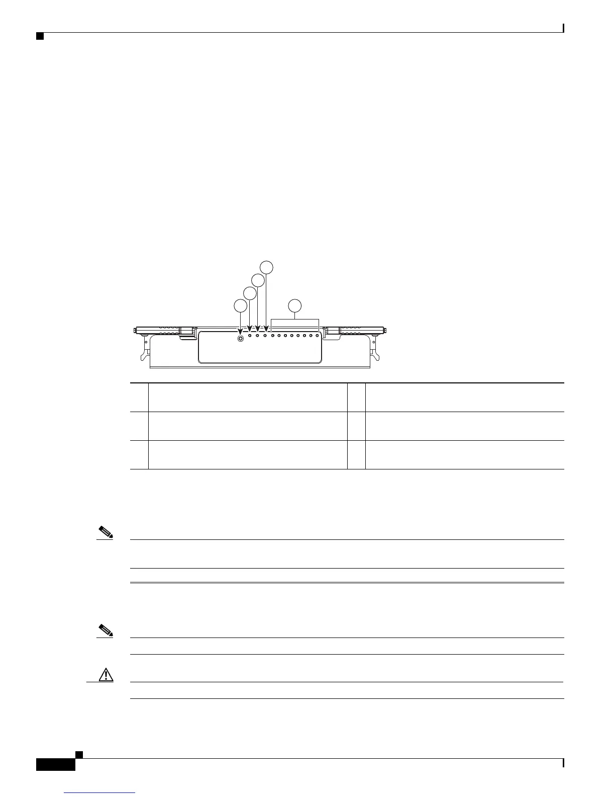
Figure 3-20 Memory Riser LEDs (Top View)
DIMM Replacement Procedure
To install a DIMM pair, follow these steps:
Note DIMM risers are hot-swappable when you use the attention button, so you do not have power off the
server or disconnect power cords. Use the following procedure.
Step 1 Remove the DIMMs that you are replacing: See Figure 3-21:
a. Slide the server out the front of the rack far enough so that you can remove the top cover.
Note You might have to detach cables from the rear panel to provide clearance.
Caution If you cannot safely view and access the component, remove the server from the rack.
b. Remove the top cover as described in “Removing and Replacing the Server Top Cover” section on
page 3-7.
1 Attention button (used for hot-swapping) 2 Attention LED (indicates when hot-swapping
is safe)
3 Power LED (indicates whether the riser has
power)
4 Mirror activity LED (indicates whether
memory mirroring is enabled)
5 DIMM fault LEDs 1 through 8
(indicate which DIMM has failed)
198939
1 5
2
3
4

 Loading...