3-29
Cisco UCS C460 Server Installation and Service Guide
OL-22326-01z
Chapter 3 Maintaining the Server
Installing or Replacing Server Components
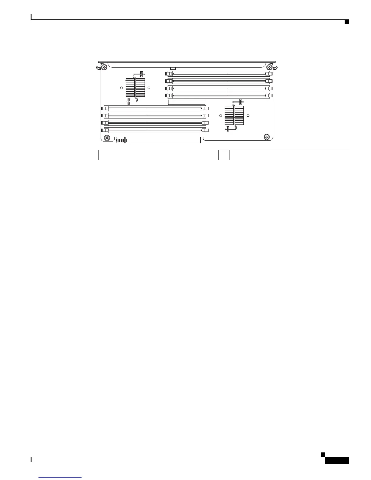
Figure 3-19 DIMM Slots and Memory Buffers
DIMM Population Rules
Following are the DIMM population rules:
• The minimum configuration for the server is, at least one matched DIMM pair installed in a memory
riser on either CPU1 or CPU2 (see
Figure 3-18). All four CPUs can run from a single DIMM pair.
• DIMMs are required to be populated in pairs. DIMMs for this server are sold as two-DIMM kits.
• The DIMMs in any given pair must be identical.
• Any DIMM installed in a memory riser corresponding to an empty CPU slot becomes inaccessible.
• For optimal performance, distribute DIMMs evenly across all installed CPUs and memory buffers.
• DIMMs within a channel are populated starting with the DIMMs farthest from the memory buffer
in a fill-farthest approach.
For example, the order that you should populate the four channels on a memory riser is as follows
(see also
Figure 3-19):
1. Slots 1B and 1D
2. Slots 1A and 1C
3. Slots 2B and 2D
4. Slots 2A and 2C
DIMM and Rank Sparing
DIMM and rank sparing can be enabled in the BIOS configuration utility.
Sparing involves utilizing one of the DIMM pairs or rank pairs within each memory riser as a spare unit.
When any of the other DIMM pairs within the same memory riser experiences errors beyond a
pre-defined threshold, it fails over to the spare DIMM pair. Spared DIMMs and ranks are hidden from
the user and the OS so that the BIOS can migrate to a spare unit when it finds degrading DIMMs.
When sparing is enabled, the available system memory is lesser than the total installed memory.
• When using DIMM sparing, the available memory equals total installed memory minus the size of
spared DIMMs.
• When using rank sparing, available memory equals total installed memory minus the size of the
spared ranks. Rank size equals DIMM size divided by the number of ranks.
1 Memory Buffer 1 2 Memory Buffer 2

 Loading...