3-32
Cisco UCS C460 Server Installation and Service Guide
OL-22326-01
Chapter 3 Maintaining the Server
Installing or Replacing Server Components
Replacing Fan Modules
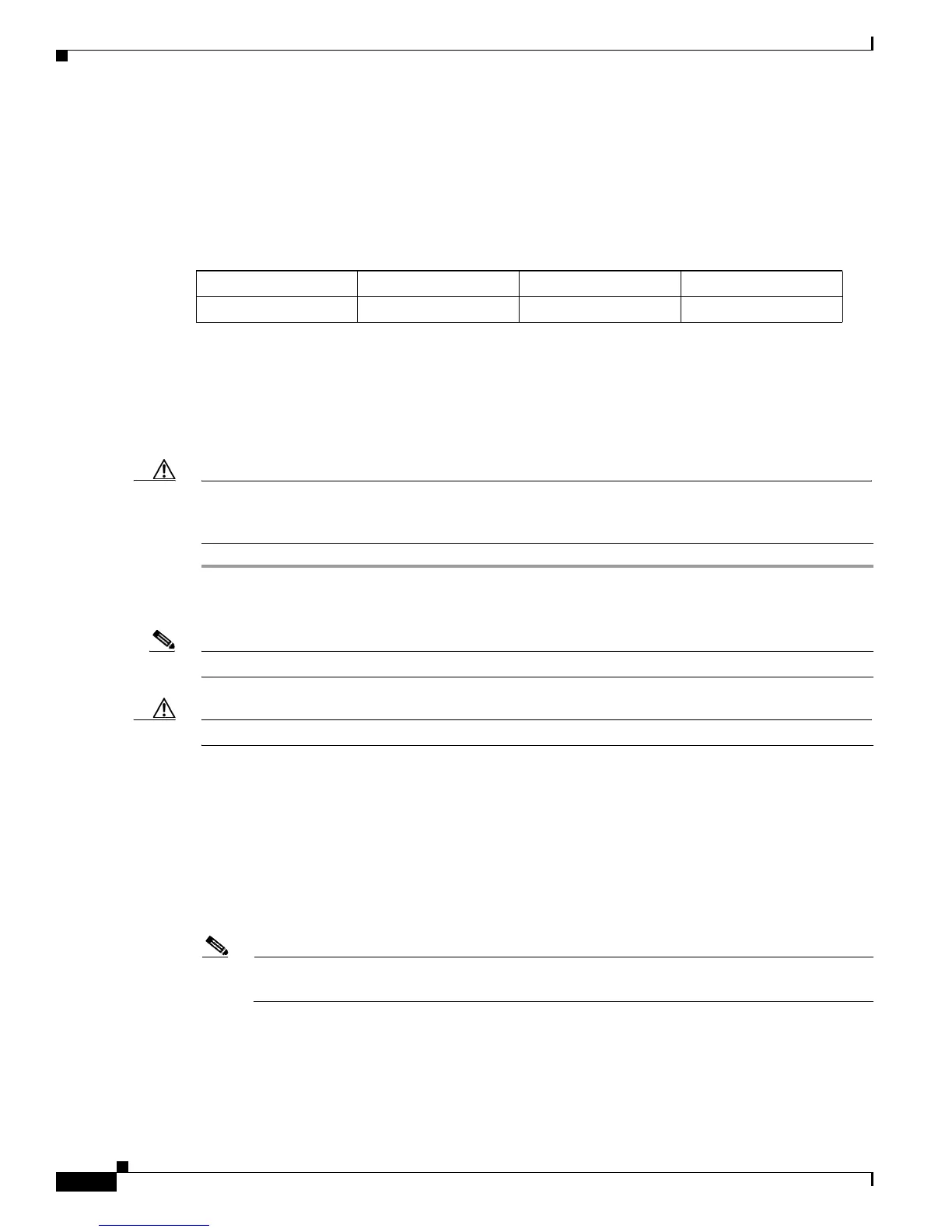
The eight fan modules in the server are numbered as follows when you are facing the front of the server.
Each fan module has a fault LED that lights amber when the fan module fails.
Figure 3-22 Fan Module Numbering
The qualified and supported part numbers for this component are subject to change over time. For the most
up-to-date list of replaceable components, see the following URL and then scroll to Technical Specifications:
http://www.cisco.com/en/US/products/ps10493/products_data_sheets_list.html
To replace or install a hot-pluggable fan module, follow these steps:
Caution You do not have to shut down or power off the server to replace fan modules because they are hot-
pluggable. However, to maintain proper cooling, do not operate the server for more than one minute with
any fan module removed.
Step 1 Remove the fan module that you are replacing: See Figure 3-23:
a. Slide the server out the front of the rack far enough so that you can remove the top cover.
Note You might have to detach cables from the rear panel to provide clearance.
Caution If you cannot safely view and access the component, remove the server from the rack.
b. Remove the top cover as described in “Removing and Replacing the Server Top Cover” section on
page 3-7.
c. Insert your thumb and forefinger in the two green release latches on top of the fan module.
d. Squeeze the release latches together and lift out the fan module.
Step 2 Install a new fan module:
a. Grasp the fan module by the release latches and align it with the empty fan bay and the motherboard
connector.
Note As you face the front of the server, the connector on underside of the fan module should be
oriented on the right-bottom side of the fan module. See Figure 3-23.
b. Press down on the top corners of the fan module until the connector is fully seated and the release
latches lock in place.
c. Replace the top cover.
d. Replace the server in the rack.
FAN 8 FAN 7 FAN 6 FAN 5
FAN 4 FAN 3 FAN 2 FAN 1

 Loading...