3-24
Cisco UCS C460 Server Installation and Service Guide
OL-22326-01
Chapter 3 Maintaining the Server
Installing or Replacing Server Components
d. Apply the new thermal pad to the center bottom of the heatsink.
e. Align the heatsink captive screws with the motherboard standoffs, then tighten the captive screws
evenly, until the screws stop against the captive springs.
Note Alternate tightening each screw evenly to avoid damaging the heatsink or CPU.
f. Replace the CPU cage. Align the six captive screws with the holes in the motherboard, then tighten
each screw evenly.
g. Replace the memory riser dividers. Slide each one into the slots on the CPU cage and the chassis.
h. Replace all memory risers. See Replacing Memory Risers, page 3-26.
i. Replace the top cover.
j. Replace the server in the rack, replace cables, and then power on the server by pressing the Power
button.
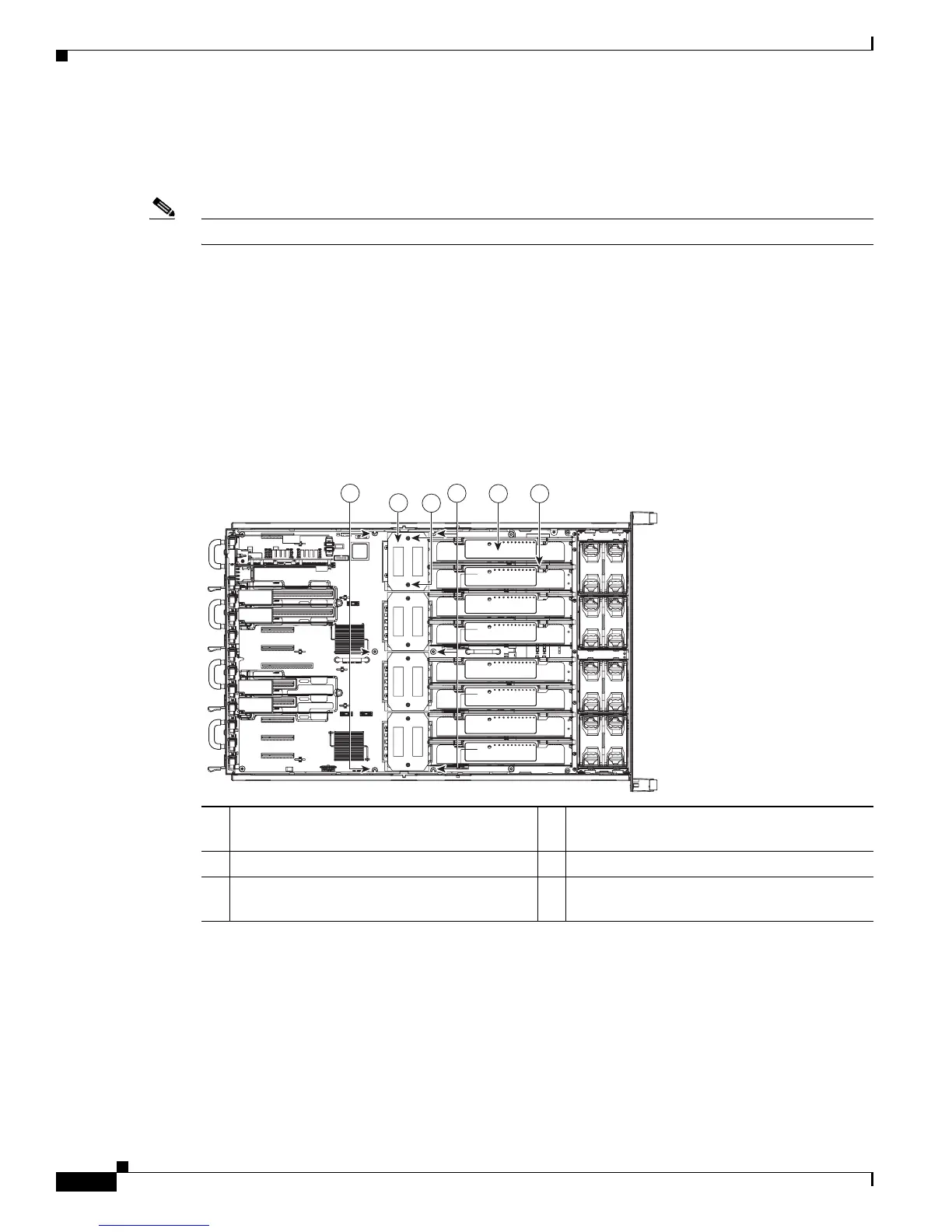
Figure 3-14 Locations of CPU Cage Screws
1 CPU cage screw locations (six) on
motherboard (cage not shown)
2 Memory risers (eight)
3 Memory riser dividers (eight) 4 CPU heatsink
5 CPU heatsink captive screws (two on each
heatsink)
2 3
4
198887
1
1
5
 Loading...