Send document comments to ucs-docfeedback@cisco.com
1-17
Cisco UCS 6100 Series Fabric Interconnect Hardware Installation Guide
OL-20036-02
Chapter 1 Product Overview
LED Descriptions
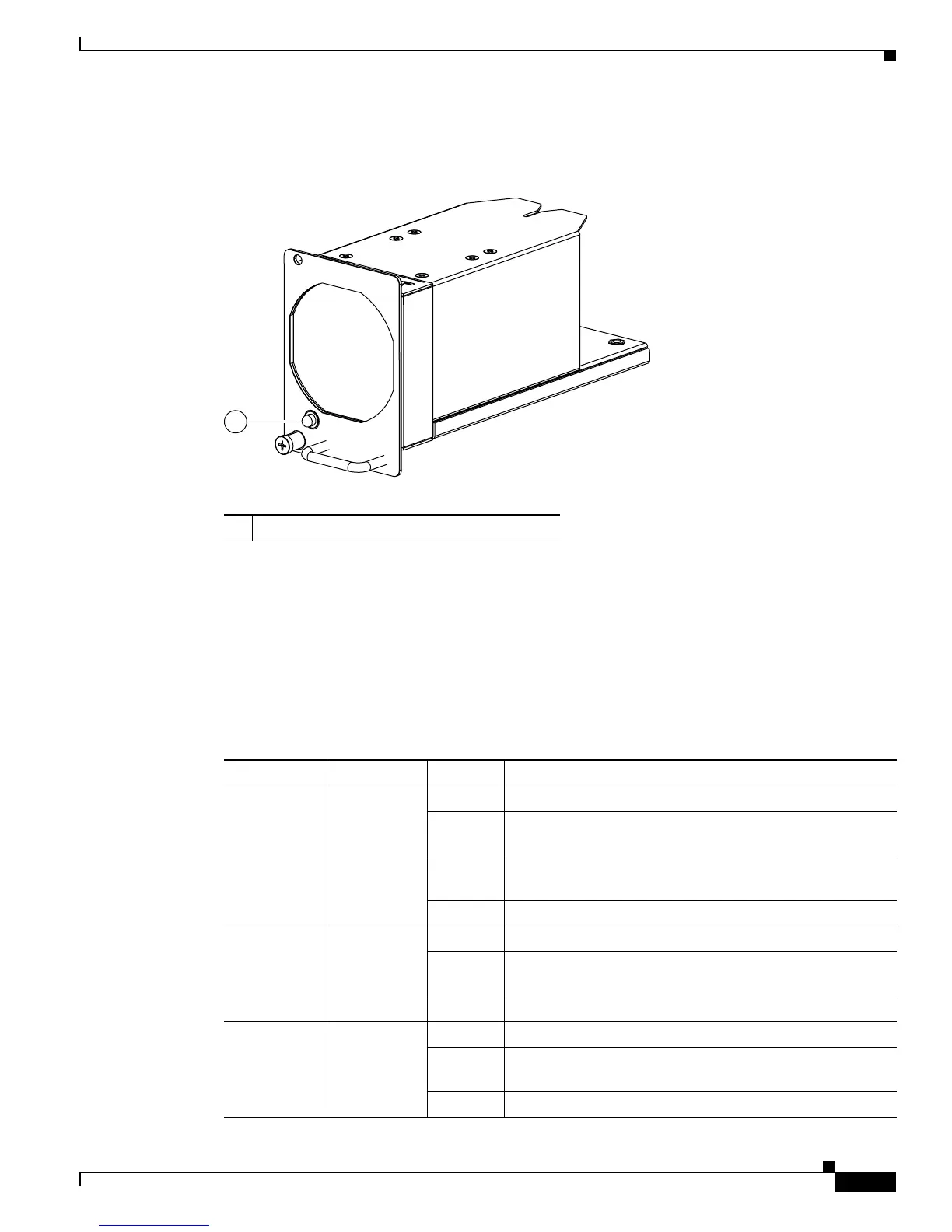
The Cisco UCS 6140XP fabric interconnect has five fan modules. Figure 1-25 shows the fan module.
Figure 1-25 Cisco UCS 6140XP Fabric Interconnect Fan Module (N10-FAN2=)
The bi-color fan module LED indicates fan tray health. Green indicates normal operation, while amber
indicates a fan failure.
LED Descriptions
Table 1-4 describes the LEDs.
1 Fan module LED
Ta b l e 1-4 LEDs for the Cisco UCS 6120XP and Cisco UCS 6140XP
LED Location Color Description
System Status Front of
chassis
Green System is operating normally.
Green
(blinking)
Standby.
Amber
(blinking)
Over temperature or major alarm.
Off System is powered off.
Fan tray Fan trays
(front of
chassis)
Green Fan tray is operating normally.
Amber
(blinking)
Fan failure is within the fan tray.
Off Not receiving power.
Power input Power supply
(front of
chassis)
Green AC power is going to the power supply.
Green
(blinking)
Receiving power, 3.3 Voltage standby (VSB) is on, power
supply is off.
Off Not receiving power.
 Loading...