Send document comments to ucs-docfeedback@cisco.com
2-26
Cisco UCS 6100 Series Fabric Interconnect Hardware Installation Guide
OL-20036-02
Chapter 2 Installing the Cisco UCS 6100 Series Fabric Interconnect
Replacing or Installing Components
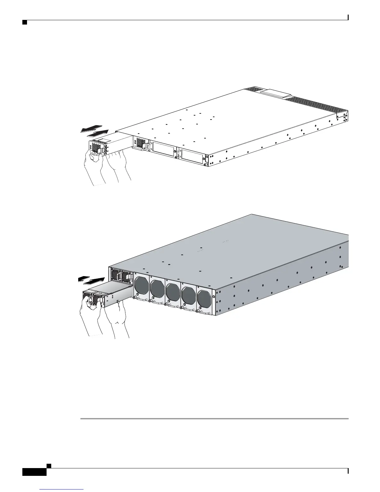
Step 3 Push against the release latch with your left thumb and slide the power supply out of the chassis. See
Figure 2-14 or Figure 2-15.
Figure 2-14 Removing the Power Supply for the Cisco UCS 6120XP
Figure 2-15 Removing the Power Supply for the Cisco UCS 6140XP
Step 4 Place your right hand under the power supply to support it while you slide it out of the chassis.
Step 5 If you are not replacing the power supply, install a blank power supply filler panel (N10-S1BLKP= or
N10-S2BLKP=). If you are replacing the power supply, see
Installing a Power Supply, page 2-26.
Installing a Power Supply
To install a power supply, follow these steps:
Step 1 Ensure that the system (earth) ground connection has been made. For ground connection instructions,
see the
“Grounding the System” section on page 2-11.
 Loading...