Send document comments to ucs-docfeedback@cisco.com
2-28
Cisco UCS 6100 Series Fabric Interconnect Hardware Installation Guide
OL-20036-02
Chapter 2 Installing the Cisco UCS 6100 Series Fabric Interconnect
Replacing or Installing Components
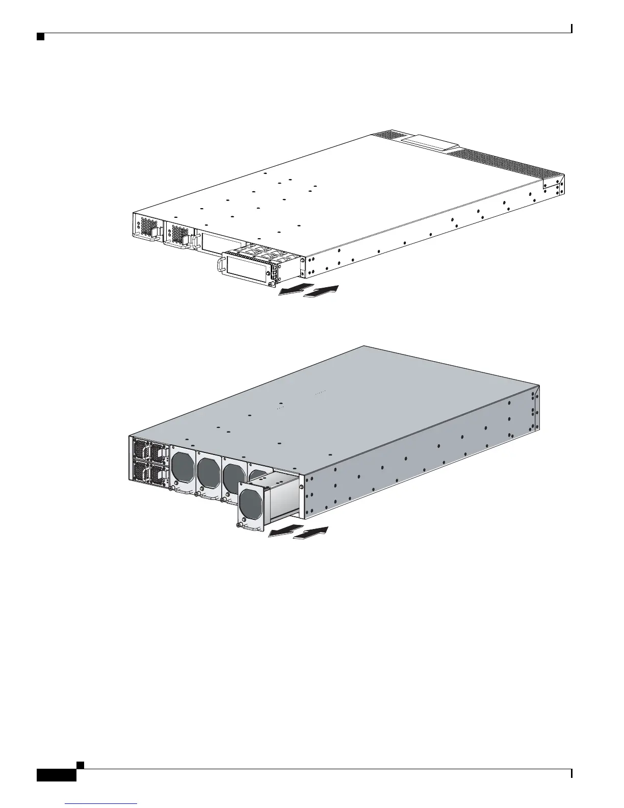
Step 3 Grasp the handle of fan module and pull it outward as shown in Figure 2-16 or Figure 2-17.
Figure 2-16 Fan Module for the Cisco UCS 6120XP
Figure 2-17 Fan Module for the Cisco UCS 6140XP
Step 4 Pull the fan module clear of the chassis and set it down on antistatic foam or place it in an antistatic bag.
Step 5 Hold the replacement fan module with the LED at the bottom.
Step 6 Place the fan module into the front chassis cavity so it rests on the chassis, and then push the fan module
into the chassis as far as it can go and the captive screw makes contact with the chassis, and tighten the
captive screw. See
Figure 2-16.
Step 7 Listen for the fans if the system is powered on. You should immediately hear them operating. If you do
not hear them, ensure that the fan module is inserted completely in the chassis and the faceplate is flush
with the outside surface of the chassis.
Step 8 Verify that the LED is green. If the LED is not green, one or more fans are faulty. If this occurs, contact
your customer service representative for a replacement part.
273164
 Loading...