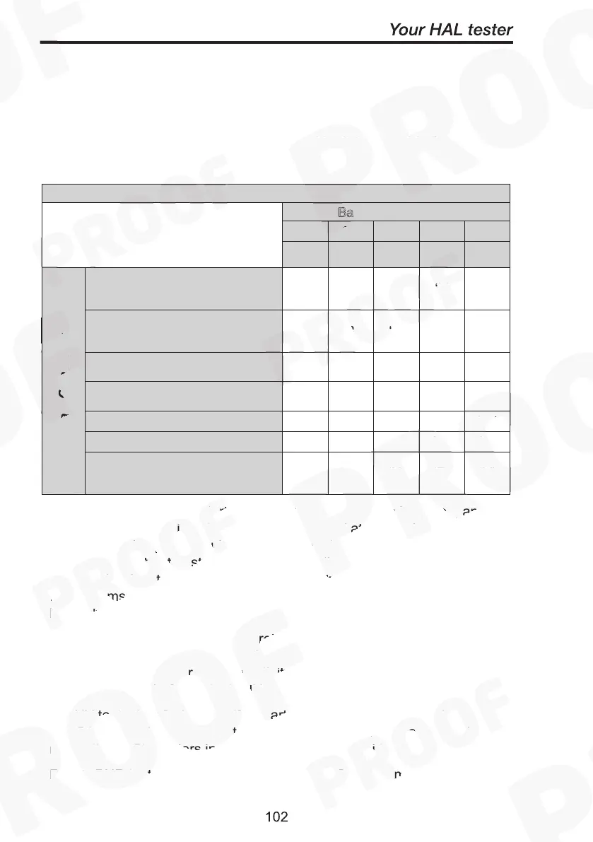
Digit 3 – Start Conditions & Base Target Voltage
Digit 3 is a combination of the start conditions for the test and the base
target voltage (to which the value encoded in digit 4 is added).
Ba
C0 C1 C2 C3 C4
0.0kV
1.6kV
3.2kV
4.8kV
Ext. guard switch opened then
closed followed by START button
(all loops)
‘0’
‘7’ ‘E’ ‘L’ ‘S’
Ext. guard switch opened then
closed followed by START button
(first loop)
‘1’
‘8’ ‘F’ ‘M’ ‘T’
Ext. guard switch opened then
closed (all loops)
‘2’
‘9’ ‘G’ ‘N’ ‘U’
Ext. guard switch opened then
closed (first loop)
‘3’
‘A’ ‘H’ ‘O’ ‘V’
START button (all loops)
‘4’
‘B’ ‘I’ ‘P’ ‘W’
START button (first loop)
‘5’
‘C’ ‘J’ ‘Q’ ‘X’
Start Conditions
None (test starts without any activity
on ext. guard switch or START
button)
‘6’
‘D’ ‘K’ ‘R’ ‘Y’
Note that no test will be started unless the guard switch is closed, and
any test in progress is automatically and immediately terminated if the
guard switch is opened during a test. Where the external guard switch
appears as part of the start conditions it implies that the GUI will wait for
the guard switch to be open for 150ms and then remain closed for at
least 150ms before the test will be started (or before the START key will
be enabled, if required).
For EBOND and PWR tests the probe's micro-switch acts in parallel to
the START button. The micro-switch must be open for at least 120ms
after any required guard switch activity is complete, and then remain
closed for 90ms before a test will be started.
For HV tests digit 3 also specifies part of the target voltage. Columns
C0, C1, C2, and C3 represent 0.00 kV, 1.60 kV, 3.20 kV, and 4.80 kV
respectively. Characters in column C4 are not permitted.
For EBOND tests only characters in column C0 are permitted.
 Loading...