Inspection and Maintenance
7-8
750-96 (revised 2010)
Model CB Packaged Boiler Manual
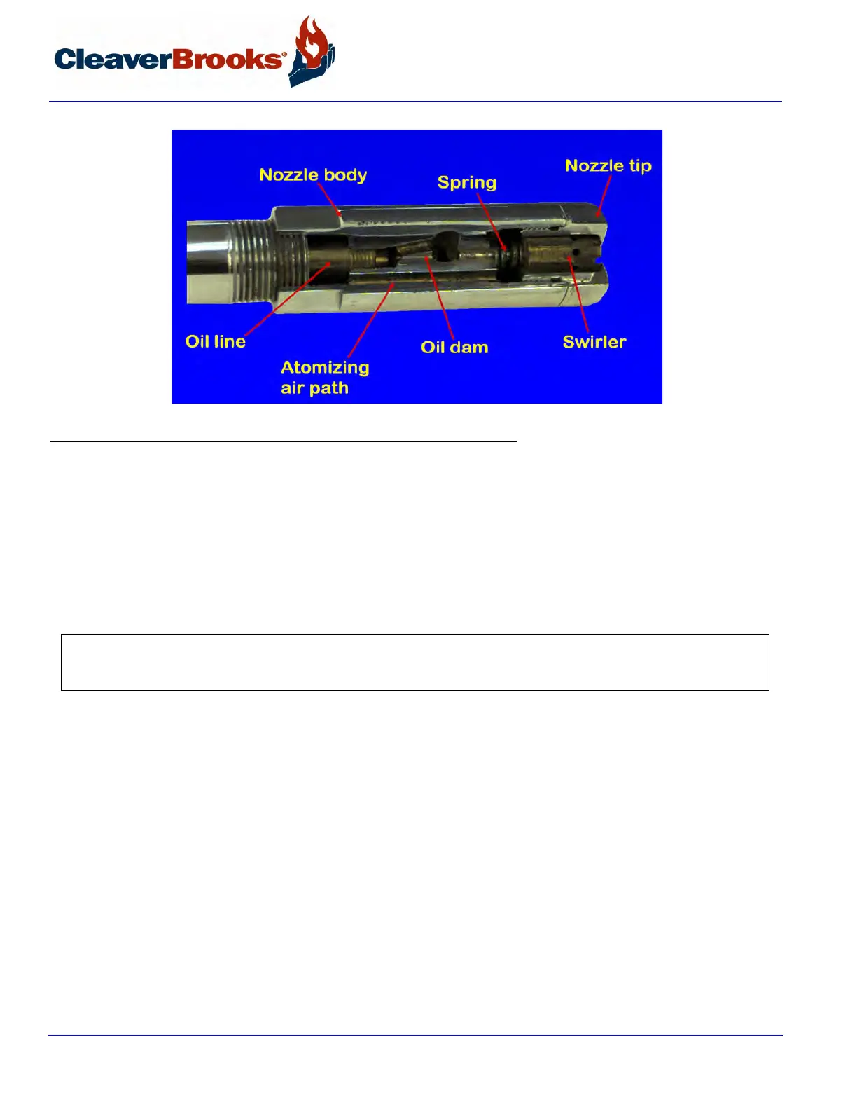
FIGURE 7-3. Burner Nozzle Assembly
Perform any necessary cleaning with a suitable solvent. Use a brush or pointed piece of soft wood for cleaning
rather than wire or a sharp metallic object which is apt to scratch or deform the orifices as well as the precision
ground surfaces of the swirler and tip. Inspect for scratches or signs of wear or erosion which may make the noz-
zle unfit for further use. Take the necessary precautions in working with solvents.
The tip and swirler are a matched set which was precision lapped at time of assembly. Do not interchange parts if
a spare is kept. In reassembling, make certain that the seating spring is in place and that it is holding the swirler
tightly against the tip. The swirler is stationary and does not rotate, but rather imparts a swirling motion to the coil.
7.7.4 — Air Purge Nozzle (No. 6 Oil), Back Pressure Orifice Nozzle (No. 2 Oil)
The nozzle and its strainer should be inspected periodically and cleaned. The nozzle consists of a tip and internal
core. Clean all internal surfaces of the tip and the slotted parts of the core using a wood splinter to avoid damage
from scratching. Replace the core, setting it tightly, but not excessively tight.
Clean the strainer screen carefully to remove any foreign matter. Use suitable solvents in cleaning. Extremely hot
water at high velocity is also helpful in cleaning. Replace the strainer by screwing it into the nozzle body only finger
tight. Do not use an orifice of a size other than originally installed.
7.7.5 — Ignition System
Maintain the proper gap and dimensions of the ignition electrode(s) for best ignition results. See Chapter 5, Sec-
tion 5.13 for correct electrode settings.
Inspect the electrode tip for signs of pitting or combustion deposits and dress as required with a fine file. Inspect
the porcelain insulator for any cracks that might be present. If there are, replace the electrode since it can cause
NOTE: The O-ring in the burner manifold block serves as a seal for the internal oil tube. It is well to replace this item
during the annual inspection. At the same time inspect the internal surface of this oil tube. See that the plugged hole is
at the bottom of the nozzle body when the gun is installed.