750-96 (revised 2010)
Model CB Packaged Boiler Manual
5-21
5.14 — Oil Drawer Switch
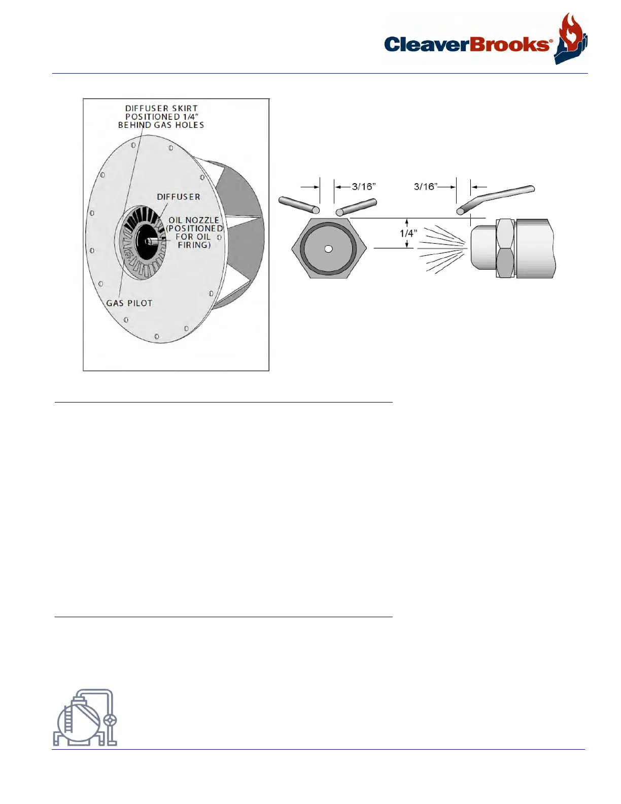
FIGURE 5-9. Diffuser and Oil Pilot Electrode
Readjust the gun locking plate, if required to obtain these settings. It is important that the oil spray does not
impinge upon the diffuser. Check the nozzle for wear and replace, if necessary, before deviating from the recom-
mended setting.
Check the setting of the ignition electrode(s) for proper gap and position. Make sure that the porcelain insulator is
not cracked and that ignition cable connections are tight.
The oil nozzle tip should be seated tightly in the body with the swirler and the seating spring in place. See Chapter
7, Section 7.7 for additional nozzle tip information.
Check to see that the flame detector sight tube and the gas pilot tube extend through their respective openings in
the diffuser face.
5.14 — Oil Drawer Switch
The integral contacts of this control are closed by proper positioning and latching of the oil drawer in its forward
position. Adjustment of the switch must be such that its contacts open if the oil drawer is not properly positioned
for oil firing. The switch is electrically removed from the circuit when a combination fuel burner is fired on gas.
Courtesy of: C3 Surplus LLC
Surplus Industrial Superstore
305-428-2777
https://www.c3surplus.com