Adjustment Procedures
5-20
750-96 (revised 2010)
Model CB Packaged Boiler Manual
4. Repeat this process, stopping at each adjusting screw until low fire position is reached. If all screws are prop-
erly adjusted, none will deviate from the general overall contour of the cam face.
5.13 — Burner Drawer Adjustment
There are relatively few adjustments that can be made to the burner, however, a check should be made to see that
all components are properly located and that all holding screws are properly tightened.
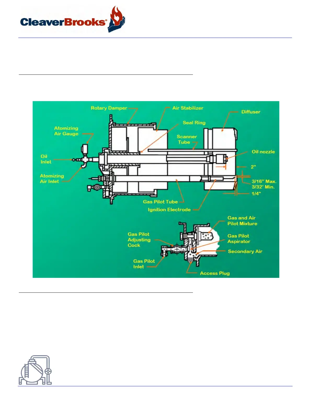
FIGURE 5-8. Burner Drawer with Gas Pilot
The diffuser location on gas fired boilers is quite important. There should be 1/4” distance between the inside
edge of the gas exit holes in the burner tube and the skirt of the diffuser. The setting of an oil fired burner is less
exacting and the diffuser should be located with skirt approximately 1” from the end of the burner tube.
Check the location of the nozzle after the diffuser setting is verified. CB50 through CB80 boilers have a perforated
plate attached to the spider and the nozzle should protrude 1/8” beyond this plate. Locate the nozzle approxi-
mately 3/8” behind the diffuser on CB100, CB100A, and CB125A boilers.
Courtesy of: C3 Surplus LLC
Surplus Industrial Superstore
305-428-2777
https://www.c3surplus.com