750-96 (revised 2010)
Model CB Packaged Boiler Manual
1-5
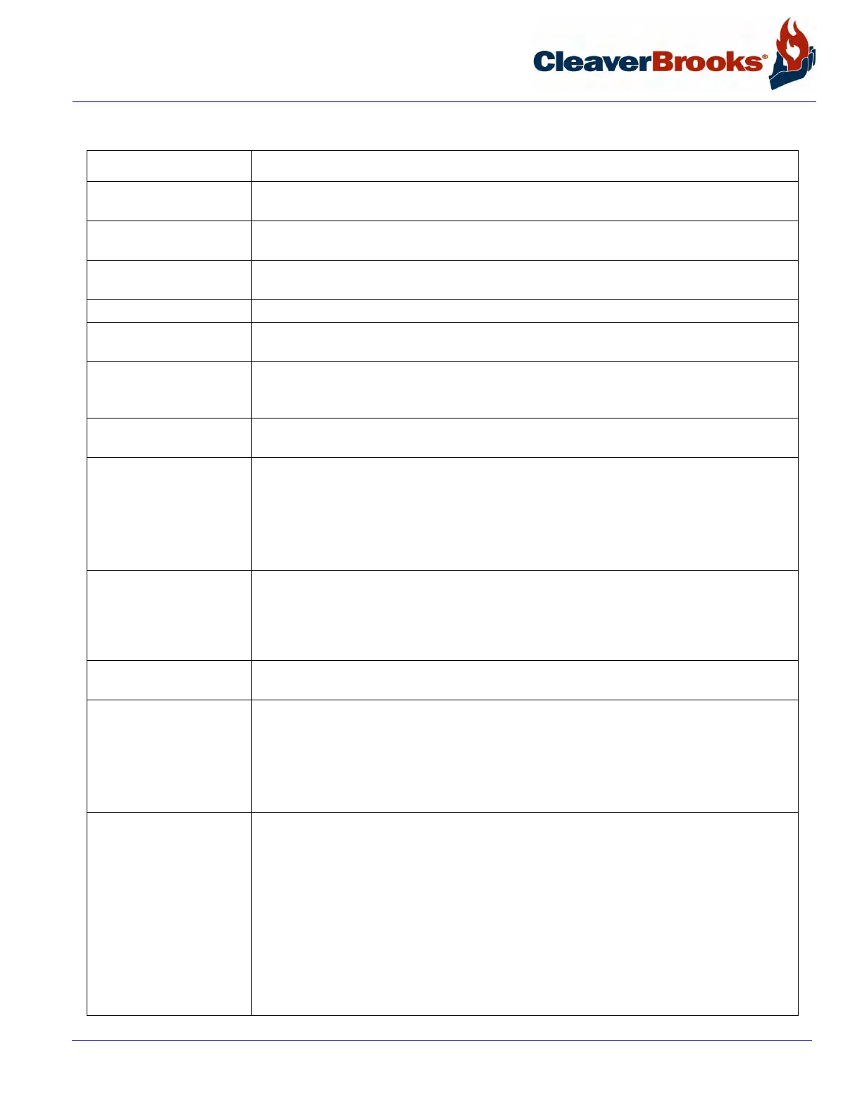
1.5 — Controls Common to All Boilers
Control Description
1. Forced Draft Fan
Motor
Drives forced draft fan directly to provide combustion air. Also referred to as a blower
motor.
2. Forced Draft Fan
Motor Starter
Energizes forced draft fan (blower) motor.
3. Forced Draft Fan Furnishes all air, under pressure for combustion of pilot fuel and main fuel, and for purg-
ing.
4. Ignition Transformer Provides high voltage spark for ignition of gas pilot or light oil pilot.
5. Modulating Motor Operates the rotary air damper and fuel valves through a cam and linkage system to pro-
vide proper air-fuel ratios under all boiler load conditions.
6. Low Fire Switch An internal auxiliary switch, cam actuated by the motor shaft, which must be closed to
indicate that the air damper and fuel metering valve are in the low fire position before an
ignition cycle can occur.
7. Burner Switch A manually operated start-stop switch for directly starting and stopping operation of the
burner.
8. Manual-Automatic
Switch
When set at “automatic,” subsequent operation is at the command of the modulating
control, which governs the position of the modulating motor in accordance with load
demand.
When set at “manual,” the modulating motor, through the manual flame control, can be
positioned at a desired burner firing rate. The primary purpose of the manual position is
for testing and setting the air-fuel ratio through the entire firing range.
9. Manual Flame Con-
trol
A manually operated potentiometer that permits the positioning of the modulating motor
to a desired burner firing rate when the manual-automatic switch is set on manual. It is
used primarily for initial or subsequent setting of fuel input throughout the firing range. It
has no control over the firing rate when the manual-automatic switch is set on “auto-
matic.”
10. Modulating Motor
Transfo r m e r
Reduces control circuit voltage (115V AC) to required voltage (24V AC) for operation of
the modulating motor.
11. Indicator Lights Provide visual information on operation of the boiler as follows:
* Flame Failure
* Load Demand
*Fuel Valve (valve open)
*Low Water
12. Program Relay and
Flame Safeguard Control
Automatically programs each starting, operating, and shutdown period in conjunction
with operating limit and interlock devices. This includes, in a timed and proper ignition
system, fuel valve(s) and the damper motor. The sequence includes air purge periods
prior to ignition and upon burner shutdown.
The flame detector portion of this control monitors both oil and gas flames and provides
protection in the event of loss of a flame signal.
The control recycles automatically during normal operation, or following a power interrup-
tion. It must be manually reset following a safety shutdown caused by a loss of flame.
Incorporated is an internal checking circuit, effective on every start, that will prevent
burner operation in the event anything causes the flame relay to hold in during this
period.