750-96 (revised 2010)
Model CB Packaged Boiler Manual
5-15
5.8 — Gas Fuel Combustion Adjustment
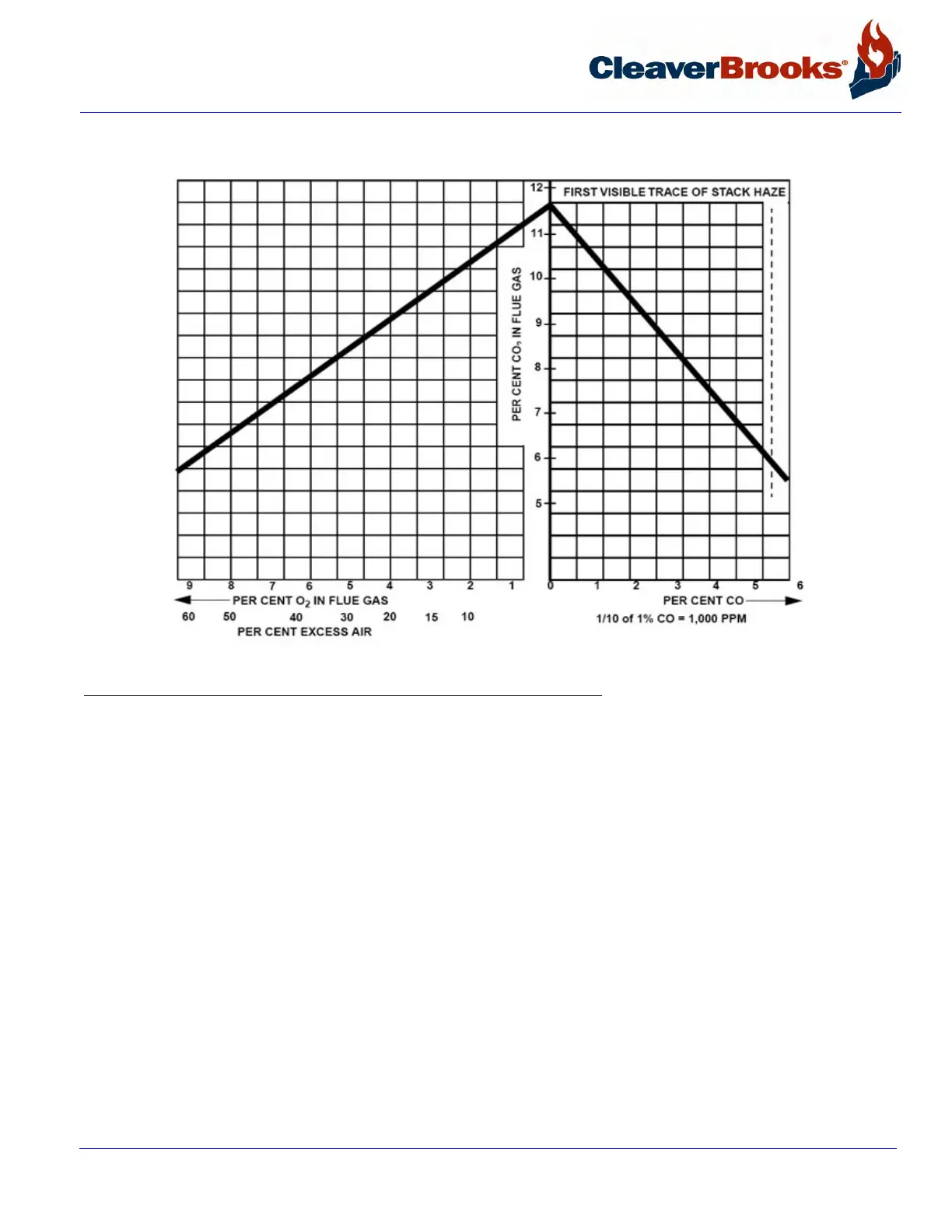
FIGURE 5-5. Flue Gas Analysis Chart for Natural Gas
Basically, gas adjustments are made with a gas pressure regulator which controls the pressure and with the butter-
fly gas valve which directly controls the rate of flow.
In initially setting the linkage, back off the low fire stop screw on the butterfly valve so that the valve is closed.
Then run the screw out to touch the arm and give it two complete turns. Adjust the connecting rod so that override
tension is released and so that the arm is now just touching the stop screw. Tighten the lock nuts on all ball joints.
This low fire setting should be regarded as tentative until proper gas pressure for high fire operation is established.
To do this, turn the manual flame control switch to “high.” At high fire position the butterfly valve should be wide
open as indicated by the slot on the end of its shaft. Set and lock the high fire stop screw until it is just touching
the valve arm.
Determine the actual gas flow from a meter reading. See Section 5.7. With the butterfly valve open and with regu-
lated gas pressure set at the calculated pressure, the actual flow rate should be quite close to the required input.
If corrections are necessary, increase or decrease the gas pressure by adjusting the gas pressure regulator, fol-
lowing manufacturer’s directions for regulator adjustment.