THE SMART SOLUTION FOR ENERGY EFFICIENCY
Tranquility
®
Compact Belt Drive (TCH/V) Series
Rev.: July 25, 2017
17
climatemaster.com
Figure 2: Horizontal Unit Pitch
1/4” (6.4mm) pitch
toward drain for drainage
Drain Connection
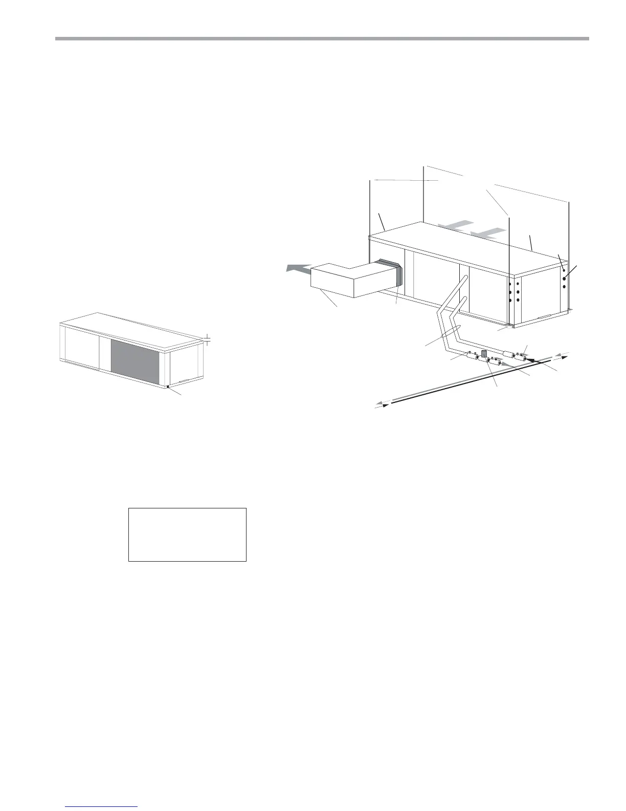
Figure 3: Typical Horizontal Unit Installation
Air Coil - To obtain maximum performance, the air coil
should be cleaned before start-up. A 10% solution of
dishwasher detergent and water is recommended for
both sides of the coil. A thorough water rinse should
follow. UV based anti-bacterial systems may damage
coated air coils.
Notice! Installation Note - Ducted Return: Many
horizontal WSHPs are installed in a return air ceiling
plenum application (above ceiling). Vertical WSHPs are
commonly installed in a mechanical room with free return
(e.g. louvered door). Therefore, fi lter rails are the industry
standard and are included on ClimateMaster commercial
heat pumps for the purposes of holding the fi lter only.
For ducted return applications, the fi lter rail must be
removed and replaced with a duct fl ange or fi lter frame.
Canvas or fl exible connectors should also be used to
minimize vibration between the unit and ductwork.
(by others)
Thermostat
Wiring
Insulated supply duct with
at least one 90 deg elbow
to reduce air noise
Return Air
Supply Air
Unit Hanger
3/8" [10mm] threaded rods
Flexible Duct
Connector
Optional
Balancing Valve
Water Out
Optional Low Pressure Drop Water
Control Valve
Stainless steel braid hose
with integral “J” swivel
Building
Loop
Water In
Ball valve with optional
integral P/T plug
Unit
Power
CAP
CAP
EAP
BSP
CBP
LEGEND
CAP=Compressor Access Panel
CBP=Control Box Panel
BSP=Blower Service Panel
EAP=Expansion Valve Access panel
1=Water Outlet 1-1/4” FPT (072-096) 1-1/2” FPT (120)
2=Water Inlet 1-1/4” FPT (072-096) 1-1/2” FPT (120)
3=Condensate 3/4” FPT
4=High Voltage 1-1/8” [2.9cm] KO
5=Low Voltage 7/8” [2.2cm] KO
NOTES:
-
All dimensions in table are inches (cm).
6HUYLFHDccess is required for all removable panels and installer should take care to comply with all building codes and
allowadequate clearance for future field service.
Water inlet and water outlet connections are available on either side (left or right) of the unit. Qty (2x) MPT Plugs are
shipped loose in a plastic bag tied to the water leg in front of the unit. Installer must plug water inlet/outlet side not being
connected to.
&RQGHQVDWHGUDLQLV)37DQGLVORFDWHGRQFDELQHWHQGRSSRVLWHWKHFRPSUHVVRU
Electrical access is available on either side (left or right) of the front.
Electric box is on right side. It can be field converted to left side. Conversion should only be attempted by qualified
service technician. If electric box relocated to opposite side, and water connected to opposite side, then this access is
not required.
Units require 3’ (9.1 cm) clearance for water connections, CAP, C%P, EAP and BSP service access.
Overall cabinet width dimensions does not include filter rail and duct flange.
8QLWVDUHVKLSSHGZLWKDLUILOWHUUDLOVWKDWDUHQRWVXLWDEOHIRUVXSSRUWLQJUHWXUQDLUGXFWZRUN$QDLUILOWHUIUDPHZLWKGXFW
PRXQWLQJFROODULVDYDLODEOHDVDQDFFHVVRU\