THE SMART SOLUTION FOR ENERGY EFFICIENCY
Tranquility
®
Compact Belt Drive (TCH/V) Series
Rev.: July 25, 2017
21
climatemaster.com
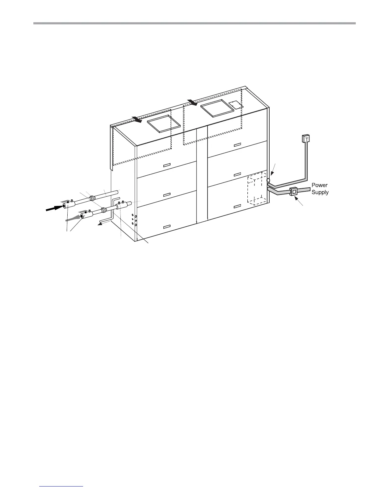
Vertical Location and Access
TC units are not designed for outdoor installation. Locate
the unit in an indoor area that allows enough space for
installation and for service personnel to perform typical
maintenance or repairs. TC units are typically installed in
a fl oor level closet or in a small mechanical room. Refer to
Figure 7 for an illustration of a typical installation. Install
units with adequate clearance to allow maintenance and
servicing. Conform to the following guidelines when
selecting unit location:
• Provide adequate clearance for filter replacement and
drain pan cleaning. DO NOT block filter access with
piping, conduit or other materials. Refer to submittal
drawing for Vertical Unit Dimensions.
• Provide access for fan and fan motor maintenance
and for servicing of the compressor and coils without
removal of the unit.
• Provide an unobstructed path to the unit within the
closet or mechanical room to enable removal of the
unit if necessary.
• Provide access to water valves and fittings, and
screwdriver access to the unit side panels, discharge
collar and all electrical connections
Figure 7: Typical Vertical Installation
Duct System Design & Installation Guidelines
The following application guidelines must be used
when installing TC units. Failure to follow these guide-
lines could result in unsatisfactory unit performance
and/or premature failure of some unit components.
ClimateMaster will not warrant, or accept responsibility
for products which fail, have defects, damage or insuffi -
cient performance as a result of improper application.
• The duct system must be sized to handle the
airflow quietly and must not exceed the maximum
allowable External Static Pressure. To maximize
sound attenuation metal supply and return ducts
should include internal insulation or be of duct board
construction for the first 10 feet or end of first full-sized
elbow.
• Install a flexible connector in all supply and return
air ducts close to the unit to inhibit sound transfer to
the ducts.
• Do not install uninsulated duct in an unconditioned
space. The unit performance will be adversely affected
and damage from condensate can occur.
Vertical Installation
Control
Box
Supply
Air
Supply
Air
Rear Return/Top Discharge shown
Refer to Dimensional Data pages for
other arrangements & dimensions
Ductwork not shown.
All components external
of unit are field supplied.
Return Air
Return Air
24 V Remote
Thermostat
Disconnect Box
Per NEC and
Local Codes
Plug water
in and out
connections
Water
In
Optional
Balancing
Valve
Return
Water
Supply
Water
Shutoff
Unions
Hoses
Optional
To
Drain
Water
Out
Condensate Internally
Trapped. Do not trap externally.
Pitch horizontal runs ¼” per foot.
(See Figure
10 for Vent)