THE SMART SOLUTION FOR ENERGY EFFICIENCY
Tranquility
®
Compact Belt Drive (TCH/V) Series
Rev.: July 25, 2017
31
climatemaster.com
Condensate Piping - TCV - Remove KO on side that
drain will be connected. Remove access panels. Inside
of unit, untie and uncoil drain hose. Form trap in hose,
make sure hose is not kinked or deformed. Connect plate
assembly to side frame with 2 screws.
Outside of unit, connect 1” MPT fi tting to plate assembly.
Run line to building drain. Horizontal runs must be
pitched ¼” per foot (10 mm per 46 cm) toward drain. Do
not trap externally.
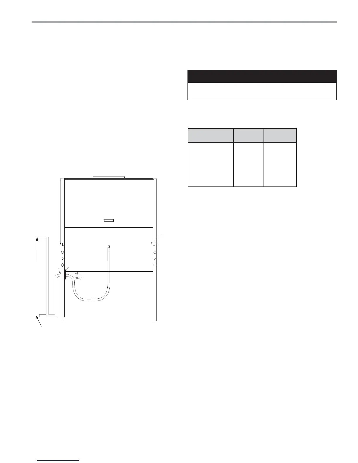
Figure 10 illustrates a typical trap and vent used with TCV
series equipment.
Each unit must be installed with its own individual line to
the building main condensate drain line or riser. Provide
a means to fl ush or blow out the condensate line. DO
NOT install units with a common trap and or vent. Always
vent the condensate line when dirt or air can collect in
the line or a long horizontal drain line is required. Also
vent when large units are working against higher external
static pressure than other units connected to the same
condensate main since this may cause poor drainage
for all units on the line. WHEN A VENT IS INSTALLED IN
THE DRAIN LINE, IT MUST BE LOCATED AFTER THE
TRAP IN THE DIRECTION OF THE CONDENSATE FLOW
and opening 46” (117 cm) minimum from bottom of unit.
(Vent per code)
m] drain slope
Pipe Connected Connected
Size Tons kW
3/4” [19mm] <4 <14
1” [25mm] <6 <21
1-1/4” [32mm] <30 <105
1-1/2” [38mm] <50 <175
2” [51mm] <150 <527
3” [76mm] <300 <1055
4” [102mm] <500 <1758
* Make sure all connections are secure and
water tight.
WARNING!
WARNING! Ensure condensate line is pitched toward drain
1/4" per foot [10mm per 46cm] of run.
Vertical Condensate Installation
All fittings and tubing outside of the unit are field supplied.
Condensate
Pan
1” IPT
2 Screws
Open
Vent
1” EPT
Fitting
46” Min
To Bottom
Of Unit
To main
drain, pitch
¼” Per foot
Figure 10: TCV
Horizontal and Vertical Installations - Drain main or
riser must be sized for all units connected to it.
After drain is connected to main and all drain
connections are secure and water tight, pour 1 gallon of
water into condensate pan. Water should drain out freely.
Repair any leaks.
• On units with multiple fan outlets a “pair of pants”
duct connection must be used for proper air balance
and distribution and to prevent fan oscillation.
• Include at least one 90-degree turn in supply air ducts
to reduce noise transmission.
• Existing ducts must be checked to ensure proper
size and configuration prior to installation of any
replacement unit. Also inspect for and repair all air
leaks in existing ducts.
• Units may only be connected to a dedicated duct
system. Consult the factory BEFORE connecting
multiple units to a common duct system.
• Never connect a unit to a duct system with automatic
or modulating dampers, VAV boxes, etc. in the supply
air system. Never allow a situation where the total unit
CFM can drop below the minimum required for proper
unit operation.
• Never connect a bypass damper from the supply air
duct to the return air duct. Never allow the return air
temperature to drop below the minimum allowable
normal temperature for proper unit operation.
• Do not use TC units for 100% outdoor air treatment.
Do not add hot-gas-bypass to “convert” a unit
for outdoor air treatment. Always use a dedicated
outdoor air unit for outdoor air treatment.
• Do not exceed 10% of the total unit CFM with
untreated outdoor air.