THE SMART SOLUTION FOR ENERGY EFFICIENCY
Tranquility
®
Compact Belt Drive (TCH/V) Series
Rev.: July 25, 2017
37
climatemaster.com
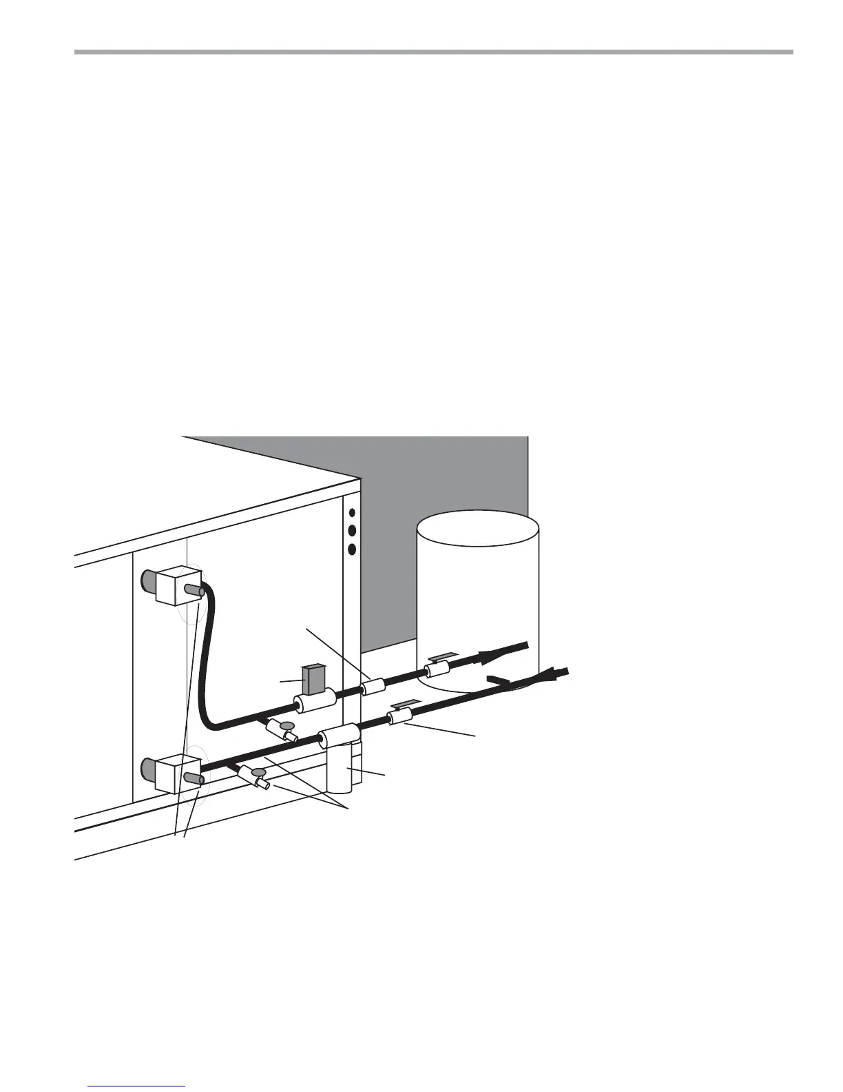
Figure 14: Typical Open Loop/Well Application
Shut-Off
Valve
Boiler
Drains
Flow
Regulator
Water In
Water Out
Water
Control
Valve
Optional
Filter
P/T Plugs
Pressure
Tank
Flow Regulation - Flow regulation can be accomplished
by two methods. One method of fl ow regulation involves
simply adjusting the ball valve or water control valve on
the discharge line. Measure the pressure drop through
the unit heat exchanger, and determine fl ow rate from
Tables 8a through 8e. Since the pressure is constantly
varying, two pressure gauges may be needed. Adjust the
valve until the desired fl ow of 1.5 to 2 gpm per ton [2.0
to 2.6 l/m per kW] is achieved. A second method of fl ow
control requires a fl ow control device mounted on the
outlet of the water control valve. The device is typically
a brass fi tting with an orifi ce of rubber or plastic material
that is designed to allow a specifi ed fl ow rate. On
occasion, fl ow control devices may produce velocity noise
that can be reduced by applying some back pressure
from the ball valve located on the discharge line. Slightly
closing the valve will spread the pressure drop over both
devices, lessening the velocity noise. NOTE: When
EWT is below 50°F [10°C], 2 gpm per ton (2.6 l/m per
kW) is required.
Water Coil Low Temperature Limit Setting - For all
open loop systems the 30°F [-1.1°C] FP1 setting (factory
setting-water) should be used to avoid freeze damage to
the unit. See “Low Water Temperature Cutout Selection”
in this manual for details on the low limit setting.