22
00001996 (REV AC) 627NH October 2014
If allowed to cool, the solid state switch will return to normal
operation. However, before returning the hoist to service,
the following procedure should be used to determine if the
switch has been damaged.
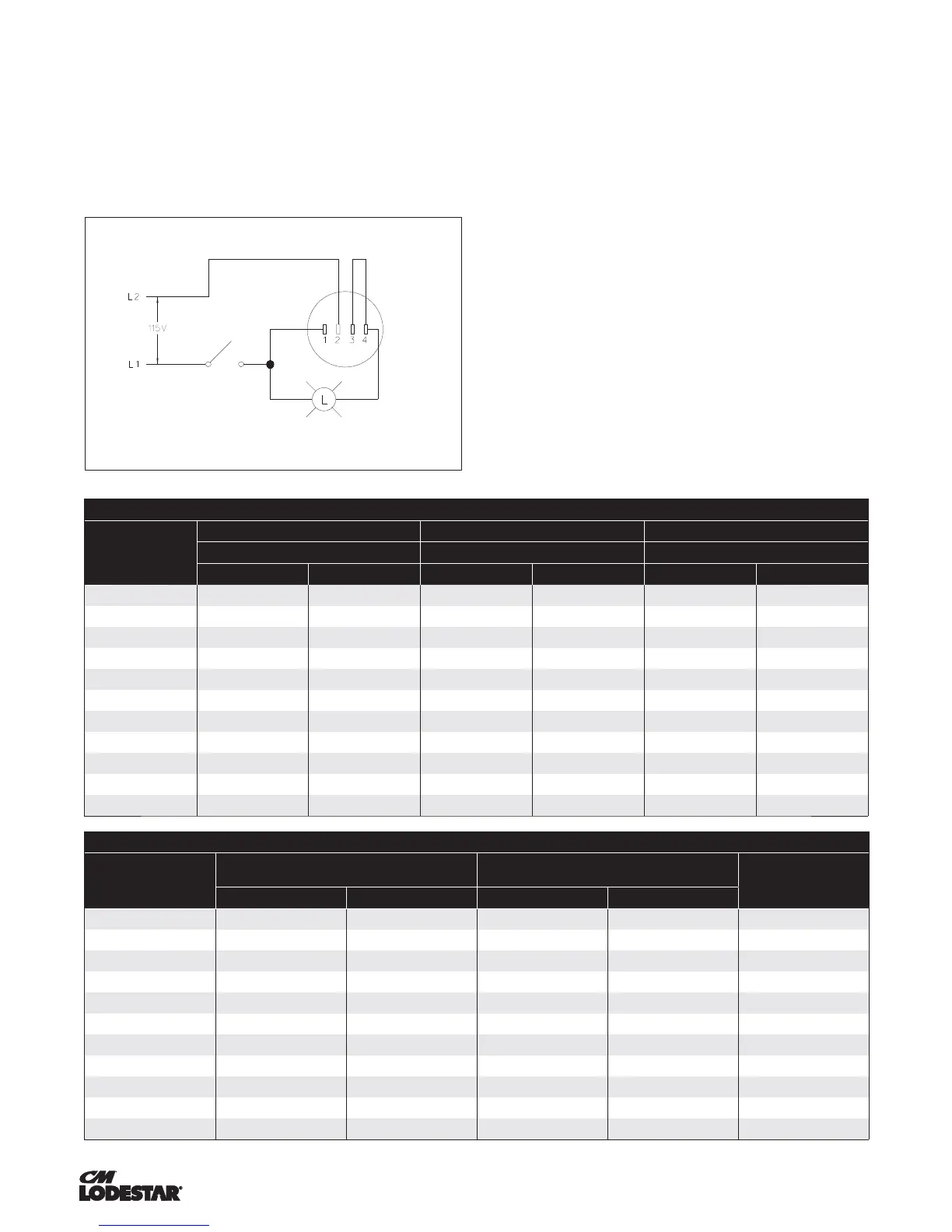
1. De-energize the power system supplying the hoist and
remove the solid state reverse switch.
2. Connect the solid state reverse switch to a 115-1-60/230-
1-60 light circuit as shown below.
3. Close the switch to energize the 115-1-60/230-1-60
power supply. The light bulb will illuminate if the solid
state reverse switch is not damaged. If the bulb fails to
illuminate, the switch is damaged and must be replaced.
4. Turn the 115-1-60/230-1-60 power off and remove the
solid state reverse switch from the test circuit.
Reinstall the solid state reverse switch in the hoist and re-
connect it using the wiring diagram supplied with the hoist.
Re-energize the power system supplying the hoist and test
for proper operation. Also, ventilate the space around the
hoist and/or reduce duty cycle, excessive starting, excessive
plugging to reduce future malfunctions of the solid state
reverse due to overheating.
BRAKE ADJUSTMENTS
DC ELECTRIC BRAKE ASSEMBLY
The correct air gap between fi eld and armature is .008-.018
in (0.2-0.45 mm) for models A through H and .008-,020 in
(0.2- 0.5 mm) for models J through RRT. The DC brake is
not adjustable. As the friction material wears, the brake gap
increases. If the maximum air gap is reached, a new friction
disc/rotor should be installed.
Table 6a. Limit Switches
Model
Hook Travel w/ 44 T.P.I. Shaft (Standard) Hook Travel w/ 56 T.P.I. Shaft (Standard) Hook Travel w/ 64 T.P.I. Shaft (Standard)
Max Length of Lift Max Length of Lift Max Length of Lift
mftmftmft
A, A-2, C, C-2 63 206 80 262 91 299
AA, AA-2 117 385 150 491 171 561
B, B-2, F, F-2 32 105 41 133 46 152
E, E-2, H, H-2 16 52 20 67 23 76
L, L-2, J, J-2 39 127 49 162 56 185
JJ, JJ-2, LL, LL-2 76 250 97 318 111 363
R, R-2 20 64 25 81 28 93
RR, RR-2 38 124 48 158 55 181
RT, RT-2 13 42 16 54 19 62
RRT, RRT-T 25 83 32 106 37 121
RRS
38 125 48 159 55 182
Table 6b. Limit Switches
Model
Hook Travel, per Notch
A (minimum distance between top
of hook block and bottom of hoist)
B (minimum length of
loose end chain)
mm in mm in
A, A-2, C, C-2 52.8 2.08 38.1 1.50 6 links
AA, AA-2 98.8 3.89 50.8 2.00 6 links
B, B-2, F, F-2 26.9 1.06 38.1 1.50 6 links
E, E-2, H, H-2 13.5 0.53 44.45 1.75 6 links
L, L-2, J, J-2 30.5 1.20 38.1 1.50 8 links
JJ, JJ-2, LL, LL-2 116.8 4.60 63.5 2.50 8 links
R, R-2 15.2 0.60 63.5 2.50 8 links
RR, RR-2 29.7 1.17 63.5 2.50 8 links
RT, RT-2 10.2 0.40 63.5 2.50 8 links
RRT, RRT-T 19.8 0.78 63.5 2.50 8 links
RRS
30.0 1.18 63.5 2.50 2.50 in