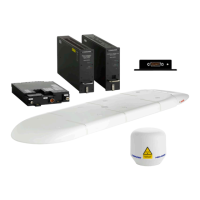
General installation information
4-2 Chapter 4: Installation 98-158751-C
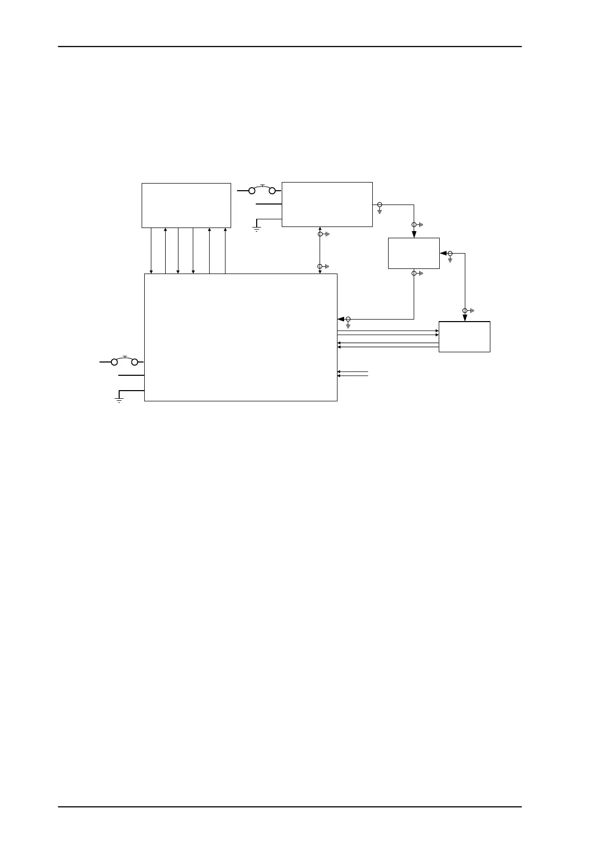
Minimum system drawing
This drawing shows which units to connect as a minimum for the system to function.
Figure 4-1: AVIATOR 700S system (minimum, AC powered)
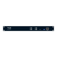
SDU-5045
CSDU
BP1 +115 VAC
Neutral (Cold)
+115 VAC
360-800 Hz
Aircraft
Power Supply
BP5 +115 VAC
Line (Hot)
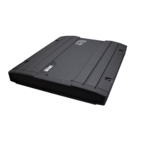
HPA-5015
MCHPA
IRS/AHRS A429 A, MP02A
IRS/AHRS A429 B, MP02B
Aircraft ARINC 429
Navigation outputs
Modem, RF RX/TX
Max. 18 dB @ 1.6 GHz
Max. 0.6 Ohm DC resistance
BP3 Chassis
Ground
TP71
RF output
SCM-5055
SCM
MP01D
MP03D
MP04D
SCM output
power
Data to SCM
(RS422 output A)
Data to SCM
(RS422 output B)
MP05D
MP06D
Data from SCM
(RS422 input A)
Data from SCM
(RS422 input B)
Pin 1
Pin 2
Pin 3
Pin 4
Pin 8
Cable length
Max. 10 m
Pin 15
MP02D
SCM power
return
DLNA
BP07
Multi Carrier: RX input
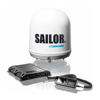
HGA
HGA Multi-Control A429 A, MP01E
HGA Multi-Control A429 B, MP01F
HGA BITE A429 A, MP08C
HGA BITE A429 B, MP08D
BP7 +115 VAC
Neutral (Cold)
+115 VAC 360-800 Hz
Aircraft Power Supply
BP1 +115 VAC
Line (Hot)
BP8 Chassis
Ground
TP71
RF Input
MP71
RF Output