Electrical installation and wiring
98-158751-C Chapter 4: Installation 4-13
Cable losses
Wiring diagram
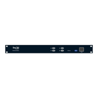
See Figure 4-1: AVIATOR 700S system (minimum, AC powered) for the wiring for
an AVIATOR 700S System with the HPA-5015 MCHPA
For the requirements to RF cable see Recommended RF cables on page 4-38 on pin TP71.
Pins for the MCHPA/CSDU
4.3.7 To wire the MCDU 1, 2 and 3
ARINC-781 compliant.
The CSDU has interfaces for three high or low speed ARINC-429 interfaces for
communication with MCDU #1, MCDU #2 and MCDU #3. For cable requirements see
Recommended cables for ARINC 429 on page 4-38.
Description
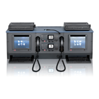
The Multi Control and Display Unit (MCDU) interfaces allow the CSDU to be managed
from a cockpit control panel. The CSDU uses MCDU protocol standards defined in
ARINC Characteristic 739 or WSCI (see ARINC 741, Part 2, Attachment 2F-42.1).
Display and control details may be manufacturer-specific.
Wiring diagram
See Wiring – overview on page 4-7.
Pins for MCDU 1, 2 and 3
Note
During installation, measure and write down the cable loss of the RF cables. See
section 4.3 for the maximum loss requirement at 1.6 GHz.
From To Description
CSDU-TP71 MCHPA-TP71 MCHPA RF input from CSDU
MCHPA-MP71 DLNA MCHPA RF output to DLNA
CSDU pin Description
MP10J Data to MCDU 1,2,3. A. (A429 output)
MP10K Data to MCDU 1,2,3. B. (A429 output)
MP01A Data from MCDU 1. A. (A429 input)
MP01B Data from MCDU 1. B. (A429 input)
MP01J Data from MCDU 2. A. (A429 input)
MP01K Data from MCDU 2. B. (A429 input)
MP10A Data from MCDU 3. A. (A429 input)
MP10B Data from MCDU 3. B. (A429 input)