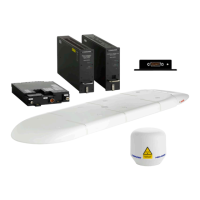
Electrical installation and wiring
4-12 Chapter 4: Installation 98-158751-C
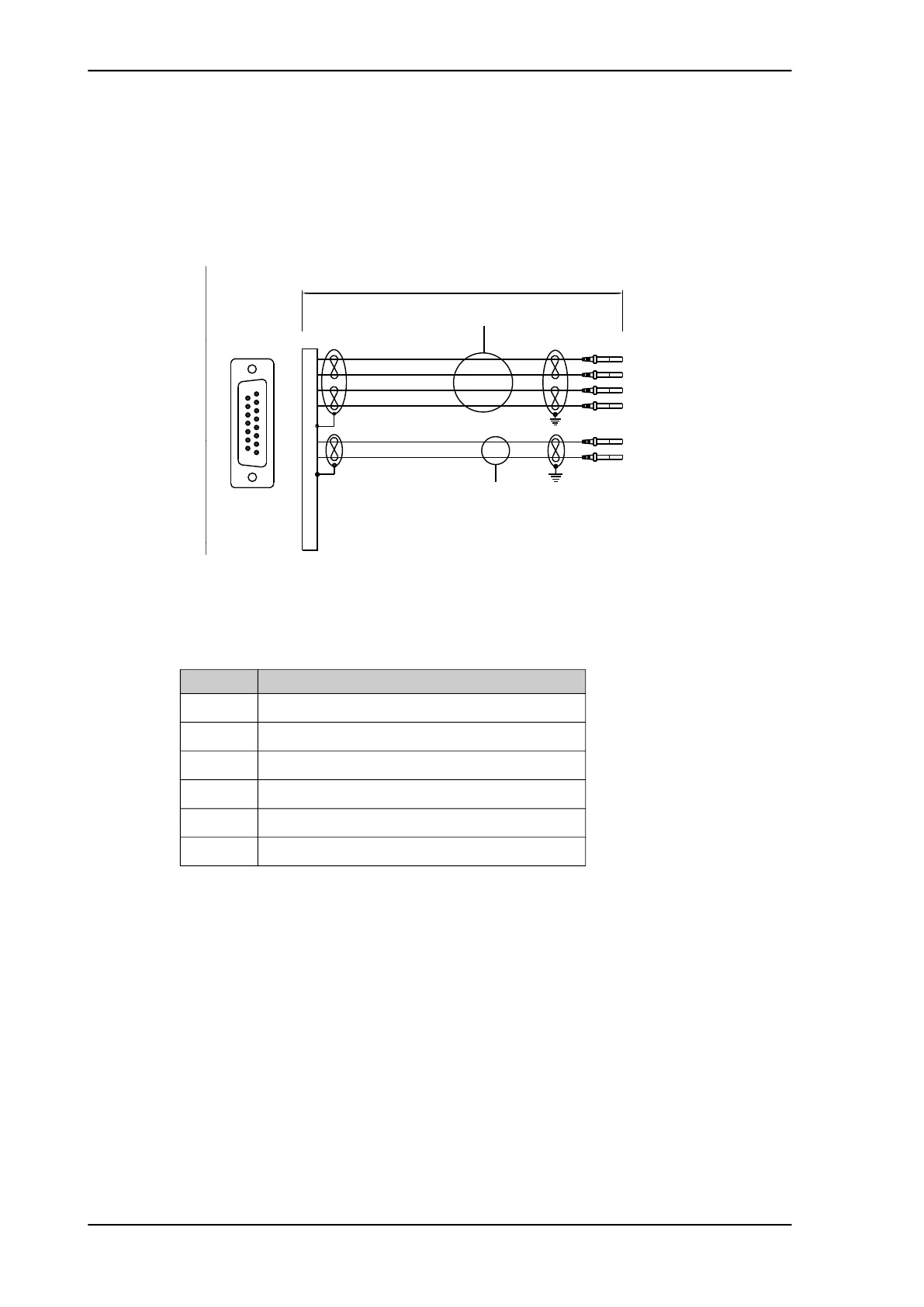
4.3.5 To wire the SCM
Wiring diagram
The following drawing shows the wiring of the SCM to the CSDU. The SCM connector
pin-out is compliant with ARINC-781.
Maximum cable length: 10 m (ARINC-781)
Pins for the SCM
Mating connector
The mating connector for use on the SCM cable harness is a 15 position D-subminiature
receptacle (sockets), MIL DTL-24308 M24308/2-2 or equivalent.
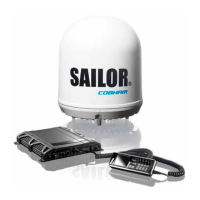
4.3.6 To wire the MCHPA
ARINC-781 compliant.
There is only one coaxial cable between CSDU and MCHPA.
Figure 4-5: To wire the SCM
10 meter
White w/blue stripe
White
8
15
3
2
1
4
MP03D
MP04D
MP05D
MP06D
MP01D
MP02D
Interconnecting Cable:
Carlisle (Thermax) M27500-22 WJ 2 S 24 (MIL-DTL-22759/86 wire)
(Silver plated shield)
Interconnecting Cable:
Carlisle (Tensolite) P/N NF24Q100-01 100Base-T Ethernet Cable.
100ohm ±10%, 13pF/ft, AVG24
Green
Yellow
Blue
Red
DB15 FEMALE
(Rear view)
8
15
1
9
CSDU pin Description
MP01D SCM Power, +8 to 18 V
MP02D SCM Power return 0V
MP03D CSDU data to SCM A
MP04D CSDU data to SCM B
MP05D SCM data to CSDU A
MP06D SCM data to CSDU A
 Loading...