Mounting considerations
98-158751-C Chapter 4: Installation 4-3
4.2 Mounting considerations
4.2.1 Overview
For optimum system performance you must follow some guidelines on where to install
the components of the AVIATOR 700S system. Installation and placement details are
included in this section.
For information on requirements to cables refer to the individual sections in Electrical
installation and wiring on page 4-6. For information on recommended cable types and
lengths refer to Recommended cables on page 4-37.
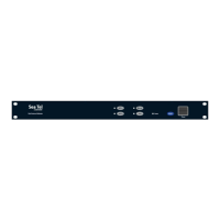
4.2.2 SDU-5045 CSDU
Installation
Install the CSDU in one of the locations described below:
• Temperature/Non-temperature controlled locations and forced airflow cooling (Tray
with fan/plenum)
• Temperature/Non-temperature controlled location and supplied airflow cooling (Tray
integrated onto a shelf rack system)
• Pressurized/Non-pressurized locations.
Mount the CSDU in a suitable tray, refer to Figure 3-8: Outline drawing:
CSDU/MCHPA tray and Figure 3-9: CSDU ARINC 600 tray connector.
Coolant air pressure drop through the CSDU (ARINC 600 Equipment Level 1)
Install the CSDU in a location with forced cooling.
The CSDU dissipates approximately 40 W and requires air at a flow rate of 26 kg/hr at a
maximum of 70°C. This leads to a pressure drop of roughly 20 Pa (2 mm water, within
the 5 ±3 mm of water specification of ARINC 600 [4], Level 1).
Ground bonding
1
1. Make the grounding wires shorter than 150 mm from grounding start at cable to crimp
terminal lugs.
2. Make the grounding wires as short as possible.
When you combine ground wires it is necessary that the combined wires are as short as
possible.
Requirements for combined grounding wire for cockpit audio
1. Crimp with: Contact size: #22, R/R Crimp PIN contacts P/N: AC-772222-301
Note
When mounting the units, give enough space for a sufficient bend radius for the
cables. Refer to the cable data sheet for minimum bend radius.
1. Source: 97-146191.