Electrical installation and wiring
4-22 Chapter 4: Installation 98-158751-C
Description
This interface is test purposes only and is only accessible when the aircraft is in Flight
Test mode.
Wiring diagram
See Wiring – overview on page 4-7
Pins for Ethernet 5 (ACD#2)
4.3.25 To wire the Maintenance interfaces
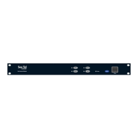
SDU-5045 Compact Satellite Data Unit
The CSDU Front Panel Ethernet interface is for shop maintenance use only and disabled
for general use.
The following drawing shows the wiring of the Maintenance PC connection on the CSDU
front via Micro USB.
CSDU pin Description
MP06E Ethernet 5 (Spare) from CSDU to User +
(ACD#2)
MP07E Ethernet 5 (Spare) from User to CSDU +
(ACD#2)
MP06F Ethernet 5 (Spare) from CSDU to User - (ACD#2)
MP07F Ethernet 5 (Spare) from User to CSDU - (ACD#2)
Important
Make sure that there is no cable connected to the CSDU Maintenance
connector when the aircraft is airborne.
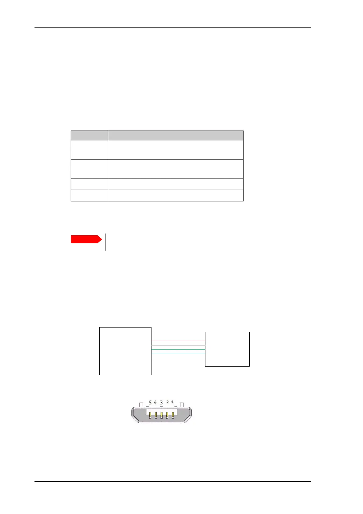
Figure 4-6: Wiring Maintenance PC via Micro USB
CSDU
1
2
3
4
5
Maintenance
PC
Micro USB
1
2
3
4
5
VCC
D-
D+
ID – Not used
GND
Figure 4-7: Micro USB maintenance connector of the CSDU, face view of
engaging end