To assemble the EXPLORER 3075GX
98-144390-C Chapter 3: Assembly & start up 3-5
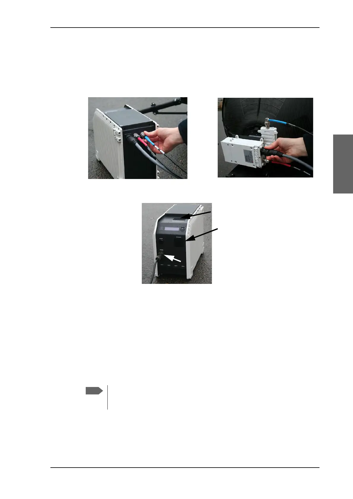
13.Connect the cables:
(1) BUC power cable (Gray) to the MIL connector
(2) Transmit (Red, Tx) cable IFL RG-6 to the BUC Transmit port
(3) Receive (Blue, Rx) cable IFL RG-6 to the LNB Receive port.
14.Connect the power cable.
15. Do not cover the GNSS (GPS, Glonass, etc.) module. The module sits in the top of the
electronics enclosure.
16.Do not cover the WLAN module.
There are four RJ-45 ports for making IP-data connections.
LAN cable type: Use shielded LAN cable.
• LAN connector on the left-hand side (LAN1) for system control via the web interface.
• Three connectors (LAN2 to LAN4) for user PCs for Internet etc., configured by the GX
modem. See the documentation from your service provider.
Figure 3-7: Transmit, Receive and BUC cables
Figure 3-8: AC power connection, location of GNSS module and WLAN module
The web interface can only be accessed via LAN1 (leftmost). The Wi-fi
connection must be configured, see To configure the LAN network on page 4-7
and WLAN settings on page 4-9.
 Loading...