Appendix A: Technical specifications
98-148232-E Interfaces specifications 115
Interfaces specifications
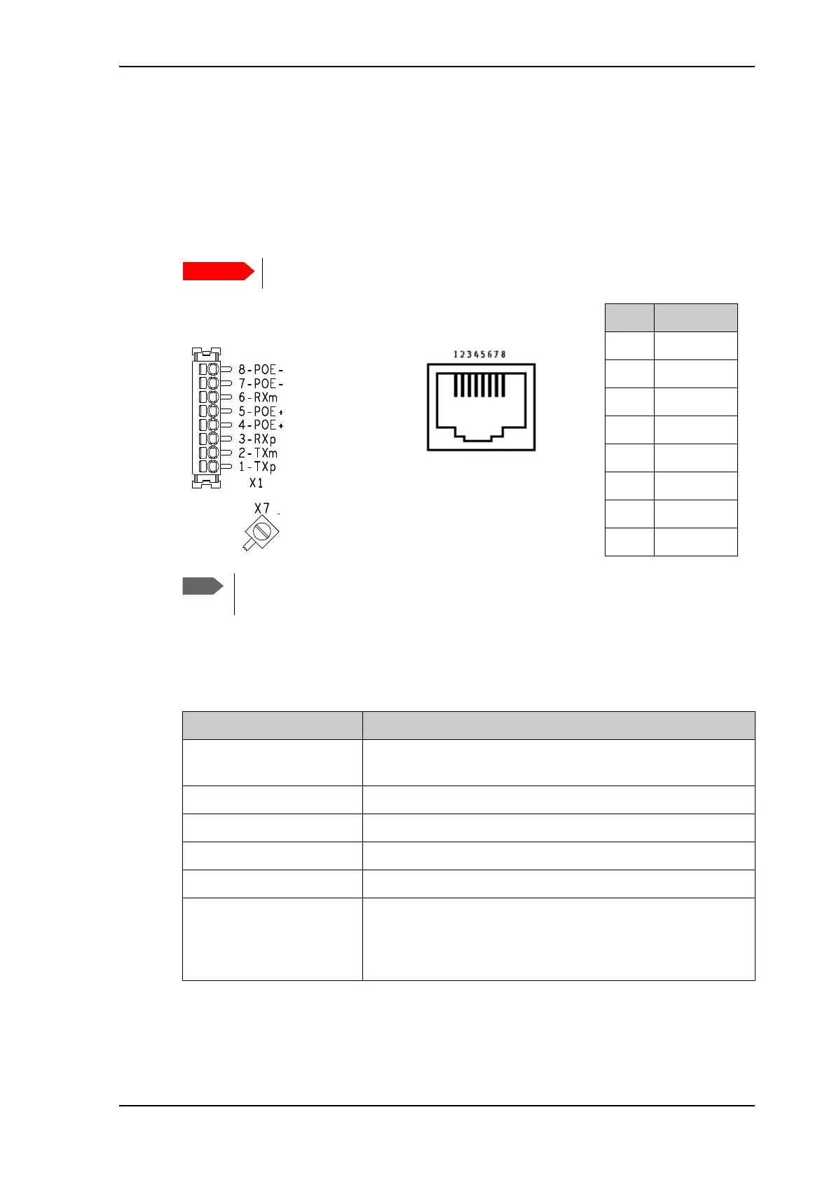
LAN interface (X1 or X2)
Connector pin-out
To insert the wires in X1 use a screwdriver (max. 2mm wide) to push each terminal open.
Specifications
There are two LAN connectors, but only one at a time can be used!
Pin Function
1TXp
2TXm
3RXp
4POE+
5POE+
6RXm
7POE-
8POE-
If you connect to the terminal block X1 you must connect the shield of the cable to
the screw terminal X7 (GND).
X1: Terminal block
and X7 (GND)
or
Female (receptacle)
X2: RJ-45 connector
and
Item Specification
Number of connectors 2: X1 or X2 - only one at a time available!
The two connectors are on the same electrical interface.
Connector types RJ-45 female or spring loaded terminals
Standard ISO/IEC 8877:1992 and PoE+ IEEE 802.3at type 2 class 4 (PD
a
)
a. The EXPLORER 540 is a Powered Device (PD), that is it may be powered by PoE from external Power
Sourcing Equipment (PSE), but it cannot supply PoE.
Max. data rate 10/100 Mbps
Max. cable length 100 m / 328 ft with Cat5 UTP
Typical power consumption
(excluding PoE injector)
b
b. If you are using the optional EXPLORER 540 LTE Modem, do not use the LAN interface to power the
EXPLORER 540. Use the DC power input instead.
Power save mode (wake on GPIO or timer): 2.4 W
Power save mode (wake on LAN): 2.3 W
Standby: 3.5 W
Transmitting: 19 W