Appendix A: Technical specifications
98-148232-E Interfaces specifications 116
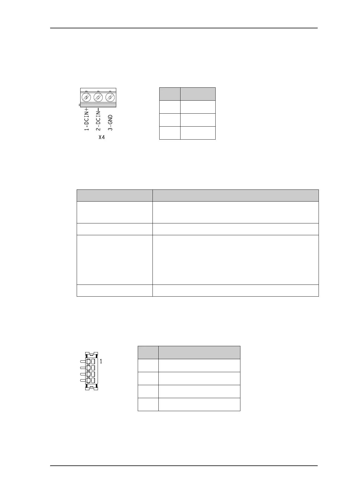
DC power input (X4)
Connector pin-out
To unscrew and fasten the screws in X4 use a screwdriver (max. 3.5 mm wide). If the DC cable
is shielded, connect the shield to pin 3, GND. Otherwise leave GND unconnected.
Specifications
I/O connector (X5)
Connector pin-out
To insert the wires in X5 use a screwdriver (max. 2mm wide) to push each terminal open.
For configuration of the I/O pins, see Power save on page 88
Pin Function
1DCIN+
2DCIN-
3GND
Item Specification
DC input range (min-max)
DC input, nominal
10.5 to 32 VDC
12 or 24 VDC
Transient overvoltage Overvoltage category II
Typical power consumption
@12 VDC supply
Power save mode (wake on GPIO or timer): 0.1 W
Power save mode (wake on LAN): 0.9 W
Standby: 1.9 W
Transmitting: 19 W (+ max. 5 W for EXPLORER 540 LTE
Modem)
Connector type Screw terminals
Pin Function
1 Request wake up (input)
2Terminal ready (output)
3 Control/Status Input/output
4GND