Chapter 2: To get started
98-148232-E Cable connections 11
Cable connections
There are no external connectors on the EXPLORER 540. All cable connections on the
EXPLORER 540 are made during installation.
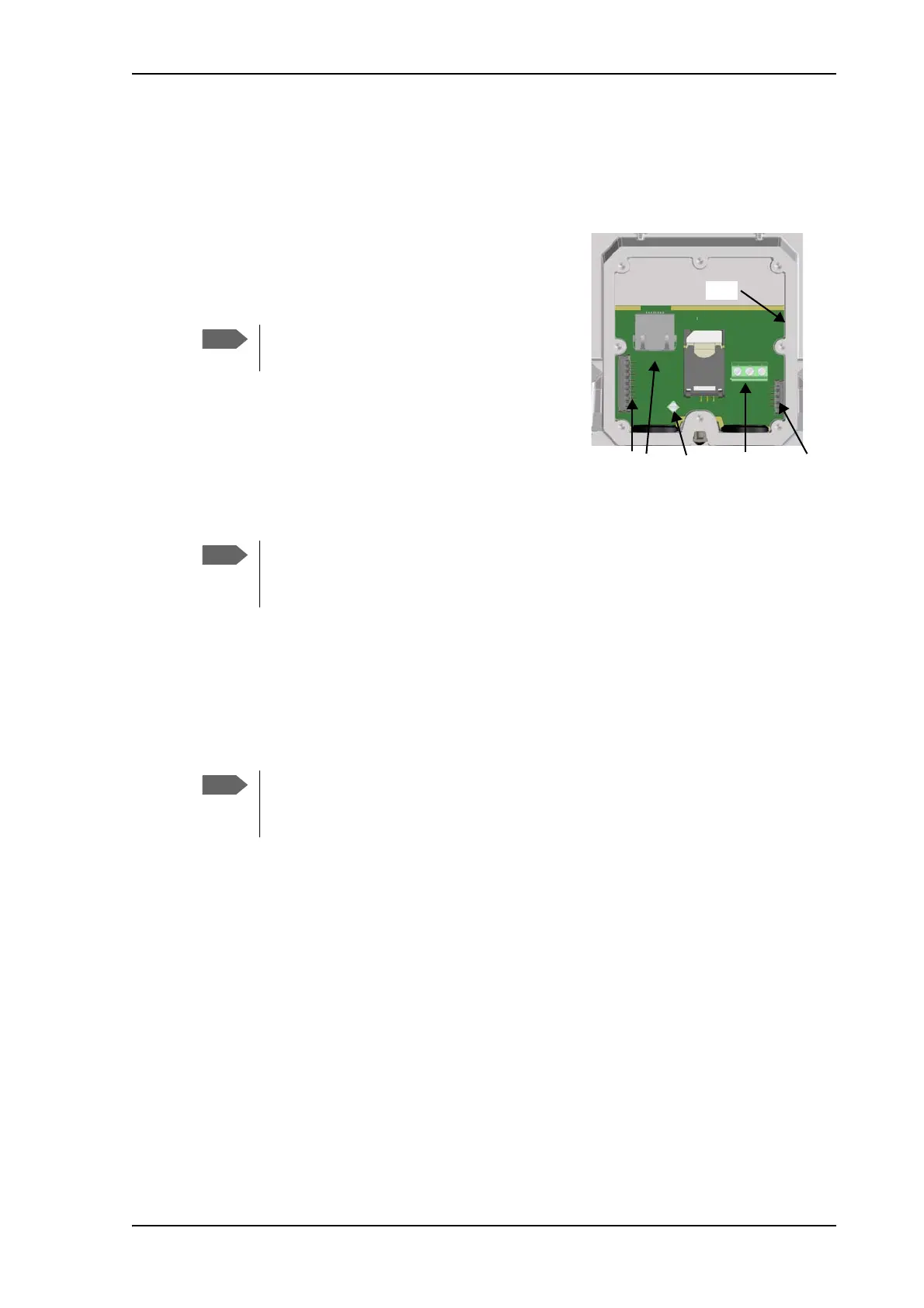
Remove the small cover at the back of the terminal and
connect the cables to the relevant terminals or
connectors. Two ATEX approved cable glands with
gaskets are provided for the cables.
See Interfaces specifications on page 115 for
specifications and pin-out for the interfaces.
See the section below for instructions specific to the DC
input.
See the EXPLORER 540 Installation guide for details on
how to connect cables in the EXPLORER 540.
Instructions for power input
Use one of the following power sources (connected at installation, see the Installation guide):
• PoE+ via the LAN interface
• 12 or 24 VDC nominal, e.g. from a battery (absolute maximum rating 10.5-32 VDC)
Requirements for DC input
Observe the following requirements for connecting to the DC input:
• Power supply: Use only fused or current limiting power supply.
•Cable requirements:
• Wire size 1.5 mm
2
, copper
• Torque for screw terminals: 4.5 lbf in
• Temperature rating: Min. 105 °C
• Max. length: 12 m at 12 VDC, 200 m at 24 VDC
• UV resistant cable
For C1D2 operation, use cable glands that
comply with NEC501.10b.
If you are going to use the optional EXPLORER 540 LTE Modem, connect the modem
to the USB connector. For details see the installation guide included with the
EXPLORER 540 LTE modem.
When you use the EXPLORER 540 with the LTE modem, a separate DC supply is
recommended instead of PoE in order to supply sufficient power for the LTE modem
as well as the EXPLORER 540.